Specifications and Site Requirements
Electrical Specifications
74 MagneMotion
Rockwell Automation Publication MMI-UM013B-EN-P - April 2020
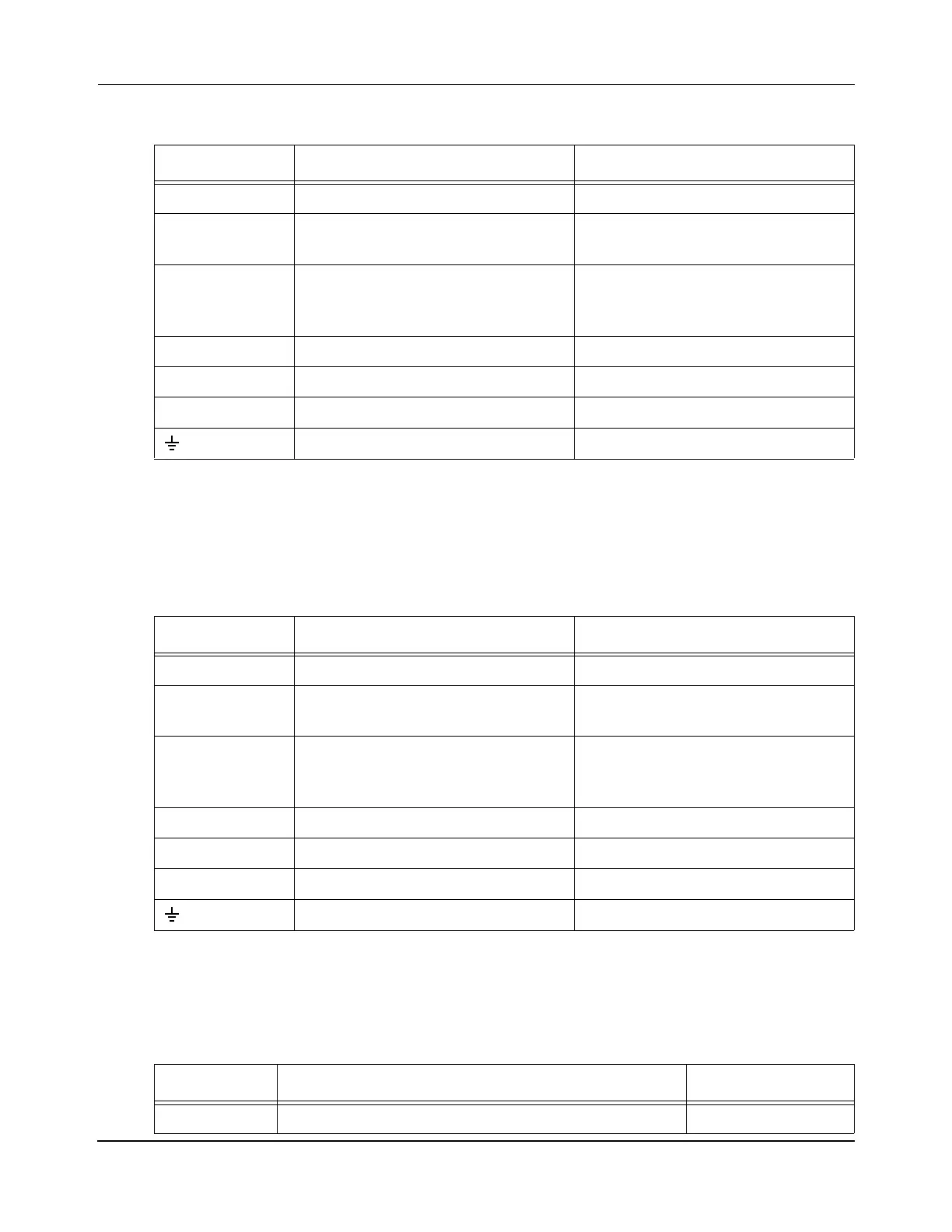
Table 4-14: NC-12 Node Controller Connections, 700-1482-00
Label Description Connector Type
CONSOLE External terminal DE-9, Male
ETHERNET Ethernet – 10/100/1000 BaseTx
(auto-MDIX, auto-negotiation)
RJ45, Female, IP67
*
* IP67 rated mating connector is not required.
DIGITAL I/O Digital I/O, optically isolated, 16
input bits and 16 output bits, see Gen-
eral Purpose Digital I/O on page 47
Spring-cage clamp
RS-232 RS-232 external communications DE-9, Male
RS-422 RS-422 motor communications M8 Nano-Mizer, 4-Pin, Male
†
† MagneMotion recommends that the odd number connectors be used for upstream connections and the even
number connectors be used for downstream connections.
POWER 22–30 VDC, 20 W DC Power Jack, 2.0 mm Coax, Male
Ground M6 threaded stud
‡
‡ MagneMotion requires grounding the NC-12 through the ground stud with a minimum of 14 AWG wire.
Table 4-15: NC-12 Node Controller Connections, 700-1573-00
Label Description Connector Type
CONSOLE External terminal DE-9, Male
ETH Ethernet – 10/100/1000 BaseTx
(auto-MDIX, auto-negotiation)
M12, Eurofast, 4-Pin, Female
DIGITAL I/O Digital I/O, optically isolated, 16
input bits and 16 output bits, see Gen-
eral Purpose Digital I/O on page 47
Spring-cage clamp
RS-232 RS-232 external communications DE-9, Male
RS-422 RS-422 motor communications M8 Nano-Mizer, 4-Pin, Male
*
* MagneMotion recommends that the odd number connectors be used for upstream connections and the even
number connectors be used for downstream connections.
LVDC 22–30 VDC, 20 W M12 Eurofast, 4-Pin, Male
Ground M6 threaded stud
†
† MagneMotion requires grounding the NC-12 through the ground stud with a minimum of 14 AWG wire.
Table 4-16: NC-12 Node Controller Indicators
Label Description Indicator Type
PWR/LVDC ON – Indicates that DC power is on. Green light

 Loading...


