ping section will stop according to their programmed braking delay. The headlight retains
its status, meaning it either stays on or off as programmed. Interior lighting remains turned
on in all coaches. Trains with continuous interior wiring and coaches with 8-point current
pick-up present no problems because they will not bridge the section isolation. The train
will stop reliably (programmed stopping distances must be compatible with the size of
the layout!). Shuttle Trains and multiple powered trains stop in the right position because
always the rst axle – even that of a driving trailer – will initiate the stopping sequence.
SIGNAL SECTIONS DURING COMPUTER OPERATION
If your layout is computer controlled via the forthcoming ROCO InterComm 10785 and the
return indicator 10787 the function of the signal module is limited to the display of the signal
aspects. By using a slow-going computer the in uence of the signal module make sure the
train stopping before a signal showing “STOP”.
Nevertheless the signal module ful lls an important function because when using multiple-
aspect signals the signal module will save the application of several relays. The software of
the InterComm supports the direct selection of the signal indications by providing appropriate
screen-symbols at the selector board or track display.
The prototypical stopping of the trains is done by the computer software providing a fast-go-
ing computer. It is informed by the return indication when the train has arrived at the position
where the braking action must be initiated. It will send then the correct command to the train.
PROGRAMMING OF THE SIGNAL MODULE
Before being used on your model railway it is necessary to program your signal module to
“know” to which address it should respond. To do this you connect the module to the track
out of the control ampli er. You select on the Turnout Keyboard 10770/RouteControl 10772/
10872 one of the four addresses to which the signal module should respond by pressing the
key next to the green LED. The signal module recognizes the switch command and accepts
the address as its own. The module will indicate this by having the lights of a connected signal
illuminate brie y and then will illuminate all lights in sequence. This concludes the program-
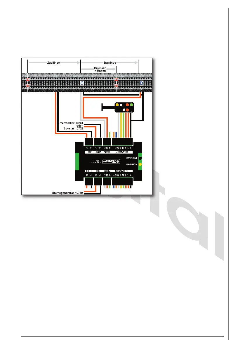
Figure 5
Connection of a 4-aspect to
the signal module 10777 with
automatic function and brake
generator 10779.
Caution: the drawing is not
to scale!
 Loading...