Do you have a question about the roco Z21 10808 and is the answer not in the manual?
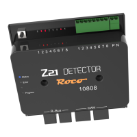
LEDs indicate occupied track sections. After commissioning, LEDs 1-4 display module address in binary for 3 sec.
Press button for 1 sec to start config. Activate magnet article with desired address. Address is accepted by detector.
Describes functions of Status (blue/off), Error (red), and Program (white) LEDs for connection, errors, and mode.
8 detector inputs as current sensors with RailCom. Current limit per section is 3A. Data cables are galvanically separated.
Occupied messages require 160ms duration. Vacant messages sent after 160ms delay to prevent false signals.
Uses dry reed contacts or switching tracks. Requires a 6.8k ohm resistor for occupied message generation.
Feedback devices measure track current. Consumers generate occupied message for the section.
Connect P/N to booster outputs. Connect 8 feedback terminals to sections. Ensure separation from both sides.
Compares CAN and R-BUS interfaces for updates, RailCom, occupied messages, configuration, and rerailing display.
Illustrates connection of Z21 Detector to the Z21 control centre via R-BUS interface.
Illustrates connection of Z21 Detector to the Z21 control centre via CAN-BUS interface.
Connect detector, provide track voltage. Press programming button for 1 sec. Activate magnet article with desired address.
| Brand | roco |
|---|---|
| Model | Z21 10808 |
| Category | Security Sensors |
| Language | English |