1.3 Boring Rods
The rods are designed to prevent them from rotating with respect to each other when they are properly
tightened. They are fitted with flats at each end so that they can be locked with an open-ended spanner. The
rods must be smooth, clean and dry (free of oil or grease) for the clutch to engage correctly. Do not use an
adjustable wrench; use the spanners supplied by the manufacturer. Always ensure that the assembled rods
are straight. To do this, rods can be rolled on a rectilinear surface to check that they are straight.
Also, ensure that they are firmly secured to each other. Rods that are not properly screwed together will
tighten up during the tests. Clean the rods thoroughly while removing them and after each use. If this is not
done, soil will build up in the clutch and recording unit, and will stop them from working.
1.4 Recording unit
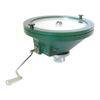
The Nilcon vane tester has a recorder which automatically marks out test curves on a waxed paper disk. The
applied torque is recorded radially and the angular rotation is recorded tangentially. The recording unit must be
kept in its steel carrying case when not in use. Keep the recording unit protected from rain and snow.
The recording unit consists of the following parts:
1. Glass removable cover
The cover is secured with two large screws. It can be taken off for installing waxed paper disks. The graph
trace can be viewed through it. The paper is held in place by a metal ring located at the centre of the glass
cover. During use, the cover must be tightened sufficiently (to prevent the needle from moving the paper), but
it must not be too tight. After use, the cover should be loosened to improve service life.
The aluminum platen must stay dry.
Avoid exposing the cover to sunlight for prolonged periods of time.
2. Slow and fast transmission axles
The slow transmission axle is for performing the shear test. The crank handle is put onto the axle for this
transmission speed after the fast transmission axle has been pulled out by about 1 cm.
The fast transmission is used to reset the needle to zero after a test. To do so, fit the crank handle onto the
pushed-in fast transmission axle to create a low transmission ratio.
The high-to-low transmission ratio is 30 : 1.
3. Clutch (Chuck)
A clutch (at the base of the recording unit) transmits the movement of the crank to the vane tester rods when it
is engaged. The clutch is the component that causes the most operating problems, mainly because of dirt build
up. It must be removed and cleaned regularly.
The clutch should be operated as follows:
Clutch with rods engaged: In this position, the spring (3) is partially released, the locking screw is offset by
about ¼ of a turn compared to the screw holding the spring and the ring is in the raised position. In order to
engageg the clutch, push the clutch’s ring up and turn it counterclockwise when viewed from above.
Clutch with rods disengaged: In this position, the spring is tensioned, the screw holding the spring and the
locking screw are vertically aligned and the ring is in the low position. To do so, turn the clutch’s ring clockwise
(when viewed from above) while lowering it (towards the ground).


 To Next Page
 Loading...