BA_D8755
Issue 03/2004
Subject to changes without notice.
Page 2/2
Any mounting position of the check valves
is possible.
! Return the leakage return port L
depressurised at the reservoir.
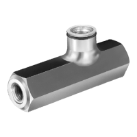
Type 2951-416 (for manifold-mounting)
! Drill holes for hydraulic oil supply and
return in the fixture.
! Grind flange surface.
! Clean the support surfaces.
! Fasten the valve with O-rings on the
fixture.
Provide the threads in the fixture.
! Connect hydraulic lines to qualifying
standards, pay attention to scrupulous
cleanness! See also Römheld data
sheets A0.100, F9.300, F9.310 and
F9.360.
! Use only fittings "screwed plug B" as
per DIN 3852 (ISO 1179).
! Do not use sealing tape, copper rings or
coned fittings.
! Check sealing of the hydraulic
connections!
Check if the hydraulic ports are tight
(visual control). The valve itself is
maintenance free.
100
200
0
100
200
300
400
500
0
2951-501
2951-417
2951-421
0
2
4
6
8
10
1002030405060
2951-417
2951-501
All figures are schematic figures.
1 2
Control pressure p
Z
for unlocking at
(p
B
= 0 bar)
∆p-Q-curves only valid for flow
from B → A and for unlocked return
line A → B
Flow resistance ∆p
[bar]
Flow rate Q [l/min]
Control pressure p
Z
[bar]
p
A
[bar]
Installation Hydraulic connection
General characteristics
Part-no. 2951-416 2951-417 2951-421 2951-501
Port A, B Ø 5 G1/4 G1/2 G1/2
Control port Z Ø 3.5 G1/4 G1/4 G1/4
Control pressure p
Z
≥ bar 0.3 p
A
+ 12 0.32 p
A
+ 12 0.12 p
A
+7 0.38 p
A
+ 12
Max. operating pressure bar 500 500 500 500
Max. flow rate l/min 20 15 55 55
Maintenance
Data sheets
Types Corresponding data sheets
2951-417,
2951-501
C2.9511
2951-416
C2.9512
2951-421
D8.755
 Loading...