EasyManua.ls Logo

Roger Technology B70-2DCHP User Manual

Roger Technology B70-2DCHP
13 pages
To Next Page IconTo Next Page
To Previous Page IconTo Previous Page
Page #3 background image
Roger Technology Swing Gate Brushless B70-2DCHP Control Panel
Quick Start Guide Extended Mode
3
STEP 4)
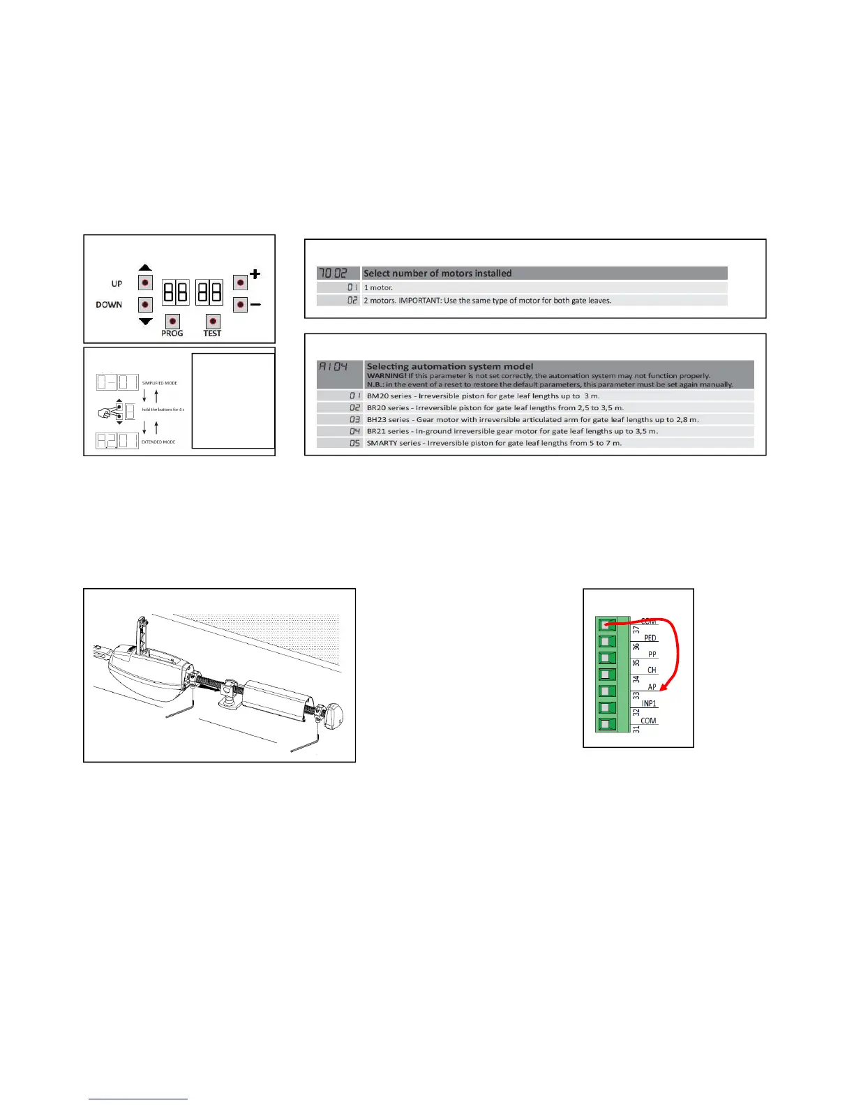
Using the control panel buttons UP/DOWN, Fig.7 Scroll down to menu 70 Fig.8 and select 1 motor or 2 motors.
Change the parameter using the + - buttons. After a few seconds the board will realise the change automatically.
From the chart in Fig.9, scroll down to A1 , select the correct parameter for the motor you have connected using the
+ - buttons, make sure the panel realises the change. It should do this again automatically after a few seconds of the
change.
(See Fig7b for B70-2DC with dual menu)
Step 5)
Using a hex key tool, and the unlock lever, set the maximum open and closed stop positions of the motor, to give the
correct corresponding gate open and closed positions for each gate as shown in Fig.10. Double check the positions
of the collars by swinging the gate open/closed with the motor unlocked.
Step
Step 6)
You should now be ready to carry out the stroke programming sequence. But first you should check that the motors
are traveling in the correct direction in relation to the control panel. To do this it will be necessary to give the panel a
brief open or close command and compare the command to the movement of the gate direction, but then quickly
turn off the power once you realise the movement. Attach a temporary cable to COM as FIG.11 then, briefly touch
the other end into the AP terminal. The AP terminal is the open command, so the gates should open. Turn off the
power to the panel as soon as you see the movement. If the gates close with the AP input, the gates are going the
wrong way. It will be necessary to swap around any two wires to the incorrect motor (ZYX) as detailed in Fig.2.
Fig.7
Fig.8
Fig.
9
Fig. 10)
Fig. 11)
Fig.7b
With (B70-
2DCHP), with dual
menu version it
may be necessary
to toggle into the
extended mode
first.
Question and Answer IconNeed help?

Do you have a question about the Roger Technology B70-2DCHP and is the answer not in the manual?

Roger Technology B70-2DCHP Specifications

General IconGeneral
BrandRoger Technology
ModelB70-2DCHP
CategoryControl Panel
LanguageEnglish

Summary

Initial Installation Steps

Step 1: Gate Preparation and Bracket Assembly

Check gates are level, free-swinging, and hinges lubricated. Assemble brackets according to manual.

Step 2: Motor Cable Connection

Connect motor cables XYZ and earth, respecting minimum 2.5mm cross-section cable size.

Step 3: Power Connection and Safety Device Configuration

Connect power, test button, and link or connect safety device inputs until display reads 00.

Photocell Integration

Photocell Installation and Wiring

Mount photocells level, 500-600mm from ground. Wire transmitter and receiver to panel.

Photocell Safety Functionality

Receiving photocell switches gate; beam break stops/reopens during closing.

Control Panel Configuration

Motor and System Model Selection

Select number of motors (menu 70) and automation system model (parameter A1).

Setting Gate Stop Positions

Use hex key to set maximum open and closed stop positions for each gate.

Motor Direction Check

Verify motor travel direction; swap wires if gates close when AP input is pressed.

Stroke Programming Sequence

Initiate programming (PROG for 4s), allow AUTO sequence for opening/closing cycles.

Radio Control and Remote Programming

Insert radio card, program remote fob buttons for full and partial gate opening.

Enabling Automatic Closing

Configure automatic closing using parameter A2 (attempts) and 21 (pause time).

Additional Connections

Gate Release Devices and Loop Detector

Connect intercoms for release and an inductive loop detector for exit.

Magnetic Locks and Time Clock Integration

Wire magnetic locks and configure 12V time clock for automated gate operation.

Safety and Compliance Guidelines (UNAC)

Installer Responsibilities and Technical File

Covers installer duties, technical file contents, CE marking, and directives.

Mechanical Risk Analysis - General

Identifies mechanical risks like impact, crushing, shearing, and assesses protection levels.

Mechanical Risk Analysis - Impact and Crushing

Details risks from impact/crushing on closing edges and force measurement criteria.

Mechanical Risk Analysis - Area-Specific

Addresses impact risks in opening/closure areas, using photocells for safety.

Electrical, EMC, and Power Failure Safety

Covers electrical safety, EMC compatibility, and safe operation during power failures.

Control, Emergency Stop, and Maintenance

Discusses control consistency, emergency stops, signalling, marking, and maintenance.