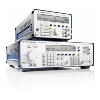
V L F > H F R E C E I V E R S
f
R & S E K 8 9 5 / R & S E K 8 9 6
User Manual
f
Control and Display Elements
yellow LED
yellow LED
Description
Upon actuation of the power switch (1)
the LED SYNTHESIZER is illuminated
during the LED test. Once the BIT is
terminated successfully, the LED goes out
(Æ CM message for the synthesizer
module).
If an error occurs after release of the
command BIT, CM or RESET, the LED will
be illuminated (see Appendix A3).
For illumination of LED SYNTHESIZER carry
out troubleshooting acc. to 4.2.
Upon actuation of the power switch (1)
the LED IF/AF PROCESSOR is illuminated
during the LED test. Once the BIT is
terminated successfully, the LED goes out
(Æ CM message for the IF/AF processor
module).
If an error occurs after release of the
command BIT or RESET, the LED will be
illuminated (see Appendix A3).
For illumination of LED IF/AF PROCESSOR
carry out troubleshooting acc. to 4.2.
Upon actuation of the power switch (1)
the LED RF UNIT is illuminated during the
LED test. Once the BIT is terminated
successfully, the LED goes out (Æ CM
message for the HF unit).
If an error occurs after release of the
command BIT or RESET, the LED will be
illuminated (see Appendix A3).
For illumination of LED RF UNIT carry out
troubleshooting acc. to 4.2.
No.
4
5
6
Control or display
element
Design
SYNTHESIZER
ZF/NF PROZESSOR
.
IF/AF PROCESSOR
HF>TEIL
.
RF UNIT
yellow LED
6164.0717.02_01
> 3.97 / 3.98 >

 Loading...