VLF - HF RECEIVERS • R&S EK 895 / R&S EK 896
User Manual • Control and Display Elements
6164.0717.02_01
– 3.101 / 3.102 –
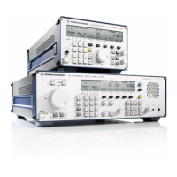
Fig. 3.2 Control and Display Elements of VLF-HF Receivers R&S EK 895 (Local)
Cursor keys:
Increases increment
Decreases increment
Increase of frequency or channel number:
turn clockwise
• Activate the freely programmed incre-
ment
Tuning knob:
• LED FRQ on: alters the frequency
• LED CH on: alters the channel number
• LED BFO on: alters the BFO frequency
• LED on: alters the frequency offset
or notch filter frequency
Increase of frequency or channel number:
• turn clockwise
Key POWER:
Switches receiver on or off
LED on: receiver switched on
Display:
• Level or tuning display
• Channel number display
• Bandwidth display
• BFO frequency display
• Frequency display
• Function or menu asignment for softkes
or
status display (CM, BIT) or
installed option display or
software display
• Control type and time display
• Modulation mode display
NOTCH
PBT
Key BFO:
LED on: BFO frequency change is enabled
Key :
LED on: frequency offset change and notch
filter frequency change are enabled
Key FREQ:
LED on: frequency change is enabled
Key CH:
LED on: channel number change is enabled
Numerical
Entry of:
• frequency
• channel number
• BFO frequency
• DGC value
• frequency offset
• start frequency
• stop frequency
• increment
keypad
• channel
• start channel
• stop channel
• dwell time
• hold time
• slave address
• IF frequency
• password
Key CLR:
• Clears an entry
• LED on: resets frequency offset to zero
Key ENT:
• Confirm an entry
• Calls up the separate function menu 1
NOTCH
PBT
RF control:
Alters the control voltage
low control voltage:
turn counter-clockwise
AF control:
Alters the volume
low volume:
turn counter-clockwise
Softkeys:
• Activate a function
• Calls up a menu
4
33
32
31
29
28
27
16
Key MENU:
Return to the next higher level
NOTCH
PBT
7
9
1
2
3
5
14
15
18
22
24
25
34

 Loading...