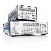
V L F - H F R E C E I V E R S
•
R & S E K 8 9 5 / R & S E K 8 9 6
User Manual
•
Troubleshooting with Control Unit 1
If all LEDs are illuminated,
• replace modules one after the other until
fault is eliminated. If the fault cannot be
remedied by this measure, send the entire
VLF-HF receiver for repair.
When the BIT has been successful, the LEDs RF
UNIT, IF / AF PROCESSOR, SYNTHESIZER, OP-
TION 1 and OPTION 2 are dark.
If the receiver does not work and the defective
module is not indicated by illumination of the
respective LED, replace the following modules
and options, if available, one after another and
check the cabling until the fault is eliminated:
• Replace processor acc. to 4.3.5.
• Replace option 'TTY Line Current Source
R&S GH 890' acc. to 4.3.10.
• Replace option 'BCD Interface R&S GC 890'
acc. to 4.3.11.
• Replace option 'Preselection
R&S FK 890H1' acc. to 4.3.12.
• Replace option 'IF Converter R&S UX 895'
acc. to 4.3.13.
• Replace option 'IF Processor R&S GM 893'
acc. to 4.3.14.
• Replace option 'Digitally Tuned RF Selector
R&S FK 896D' acc. to 4.3.15.
• Check cabling on interface X65. If ne-
cessary, close open connection and / or re-
place antenna cable.
• Check cabling on interface X66. If necessary
close open connection and / or replace line
cable.
• Check cabling on interface X63. If ne-
cessary, close open connection and / or re-
place control cable.
HF-TEIL
.
RF UNIT
ZF / NF PROZESSOR
.
IF / AF PROCESSOR
SYNTHESIZER
OPTION 1
OPTION 2
OUTPUT
RS232C - RS485
6164.0717.02_01
- 4.17 -

 Loading...