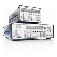
V L F > H F R E C E I V E R S
f
R & S E K 8 9 5 / R & S E K 8 9 6
User Manual
List of Figures
Fig. Title Page
A1.1 Location of Variable Resistor LINE and Test Setup . . . . . . . . . A1.7
A1.2 Test Setup . . . . . . . . . . . . . . . . . . . . . . . . . . . . . . . . . . . . . . . . . . . . . A1.9
A1.3 Location of Screws to Be Undone on Rear (R&S EK 895) . . . A1.11
A1.4 Location of Screws to Be Undone on Rear (R&S EK 896) . . . A1.13
A1.5 Arrangement of Modules and Options (R&S EK 895) . . . . . . A1.15
A1.6 Arrangement of Modules and Options (R&S EK 896) . . . . . . A1.17
A1.7 Internal Cabling . . . . . . . . . . . . . . . . . . . . . . . . . . . . . . . . . . . . . . . A1.19
A1.8 Internal Cabling (with Options) . . . . . . . . . . . . . . . . . . . . . . . . . A1.21
A1.9 Location of Jumpers on Synthesizer . . . . . . . . . . . . . . . . . . . . . A1.23
A1.10 Location of Jumper and Switches on Processor . . . . . . . . . . . A1.25
A1.11 Removal of Control Unit (R&S EK 896 only) . . . . . . . . . . . . . . A1.27
A1.12 Location of Jumpers on Control Unit (R&S EK 896 only) . . . A1.29
A1.13 Location of Jumpers on Optional
'TTY Line Current Source R&S GH 890' . . . . . . . . . . . . . . . . . . . A1.31
6164.0717.02_01
> 0A1.2 >

 Loading...