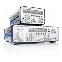
V L F > H F R E C E I V E R S
f
R & S E K 8 9 5 / R & S E K 8 9 6
User Manual
f
Cabling
BCD>INTERFACE
BFO>Reset
IF DIGITAL
OUTPUT
8. Connection of an HF selector (option)
Note:
For this the optional BCD Interfac
R&S GC!890 is required.
Connect the 25>way female connector
strip via a control cable to the control
input of an HF selector (e.g. R&S FK!101)
or HF antenna system (e.g. R&S AK 001).
Fix the trapezoidal connector strip by
means of locking screws
As mating connector we recommend the
use of a 25>way trapezoidal male connec>
tor strip, series D (FM 018.6430) and in
addition a hand>protecting housing
(FM!627.1826).
9. Connection of a data line
(digital IF signal)
Note:
How the signals depend on each other
with respect to time is described in
Appendix A2.9. For synchronization the
signal BFO>Reset (OUTPUT connector,
contact .20)
At the 5>way recessed socket the
following signals are available for further
processing:
> SFRAME
> SCLK
> SDATA
As the mating contact we recommend a
5>way cable plug, Submin>D, series 711
(FO!562.6220).
6164.0717.02_01
> 2.11 >

 Loading...