R&S
®
CMW 500 GSM Applications
GSM TX Measurements
Operating Manual 1202.3986.32 – 03 210
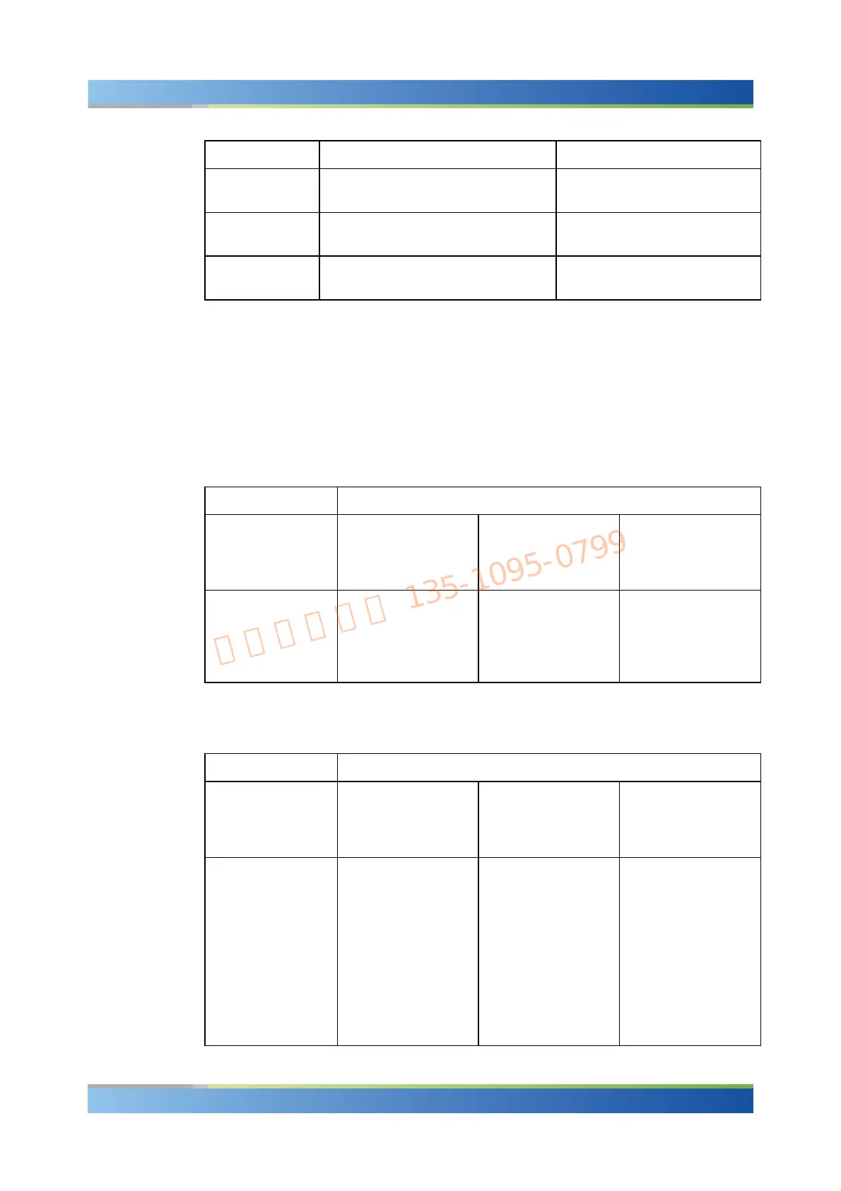
Characteristics Refer to 3GPP TS 51.010-1, section... Specified Limit
Frequency Error 13.1 Frequency Error and Phase Error
see also: 13.6, 13.16.1
< 0.2 ppm (GSM 400)
< 0.1 ppm (all other GSM bands)
Phase Error, RMS 13.1 Frequency Error and Phase Error
see also: 13.6, 13.16.1
< 5 deg
Phase Error, peak 13.1 Frequency Error and Phase Error
see also: 13.6, 13.16.1
< 20 deg
Avg. Burst Power Limits
Dynamic power control is essential to ensure stable transmission and an efficient radio
resource management within the system. Generally speaking, an output power of the
mobile transmitter that is too low decreases the coverage area while an excess output
power may cause interference to other channels or systems. Both effects decrease the
system capacity.
GSM mobile phones are divided into different power classes according to their
maximum output power.
Power class Nominal maximum output power in dBm
GSM 400
GSM GT800
GSM 850
GSM900
GSM 1800 GSM 1900
1
2
3
4
5
–
39
37
33
29
30
24
36
–
–
30
24
33
–
–
GSM power classes
The actual transmitter output power is controlled using the dimensionless Power
Control Level (PCL) scale.
Power class Nominal maximum output power in dBm
GSM 400
GSM GT800
GSM 850
GSM900
GSM 1800 GSM 1900
0
1
2
3
4
5
6
7
8
9
10
39
39
39
37
35
33
31
29
27
25
23
30
28
26
24
22
20
18
16
14
12
10
30
28
26
24
22
20
18
16
14
12
10

 Loading...


