R&S
®
CMW 500 Preparing for Use
Front Panel Tour
Operating Manual 1202.3986.32 – 03 7
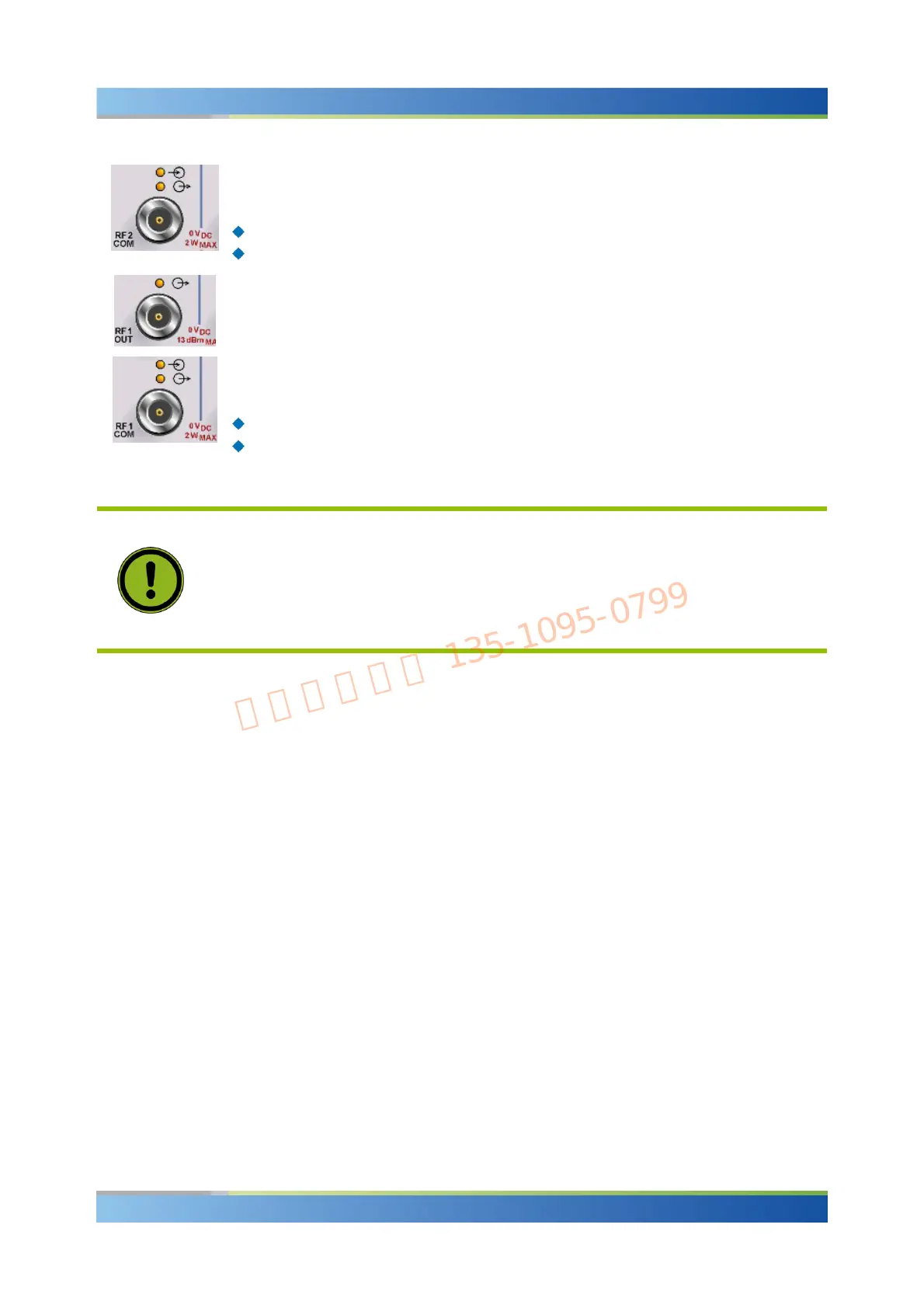
Bidirectional connector for various power ranges depending on the firmware
application (refer to the "Specifications"). The two LEDs above the connector indicate
the connector state:
The upper LED is lit as long as the R&S CMW 500 is ready to receive signals.
The lower LED is lit as long as it transmits an RF signal.
Output connector for high RF output powers depending on the firmware application
(refer to the "Specifications"). The upper LED is lit as long as the R&S CMW 500
transmits an RF signal.
Bidirectional connector for various power ranges depending on the firmware
application (refer to the "Specifications"). The two LEDs above the connector indicate
the connector state:
The upper LED is lit as long as the R&S CMW 500 is ready to receive signals.
The lower LED is lit as long as it transmits an RF signal.
ATTENTION
Maximum Input Levels
The maximum input levels at all bidirectional RF connectors according to the front
panel labeling or the data sheet must not be exceeded.
In addition, the maximum input voltages of other input connectors at the front and rear
panel must not be exceeded.
RF connectors may warm up very much when high RF power is fed in!

 Loading...


