R&S
®
CMW 500 WCDMA Applications
WCDMA TX Measurements
Operating Manual 1202.3986.32 – 03 303
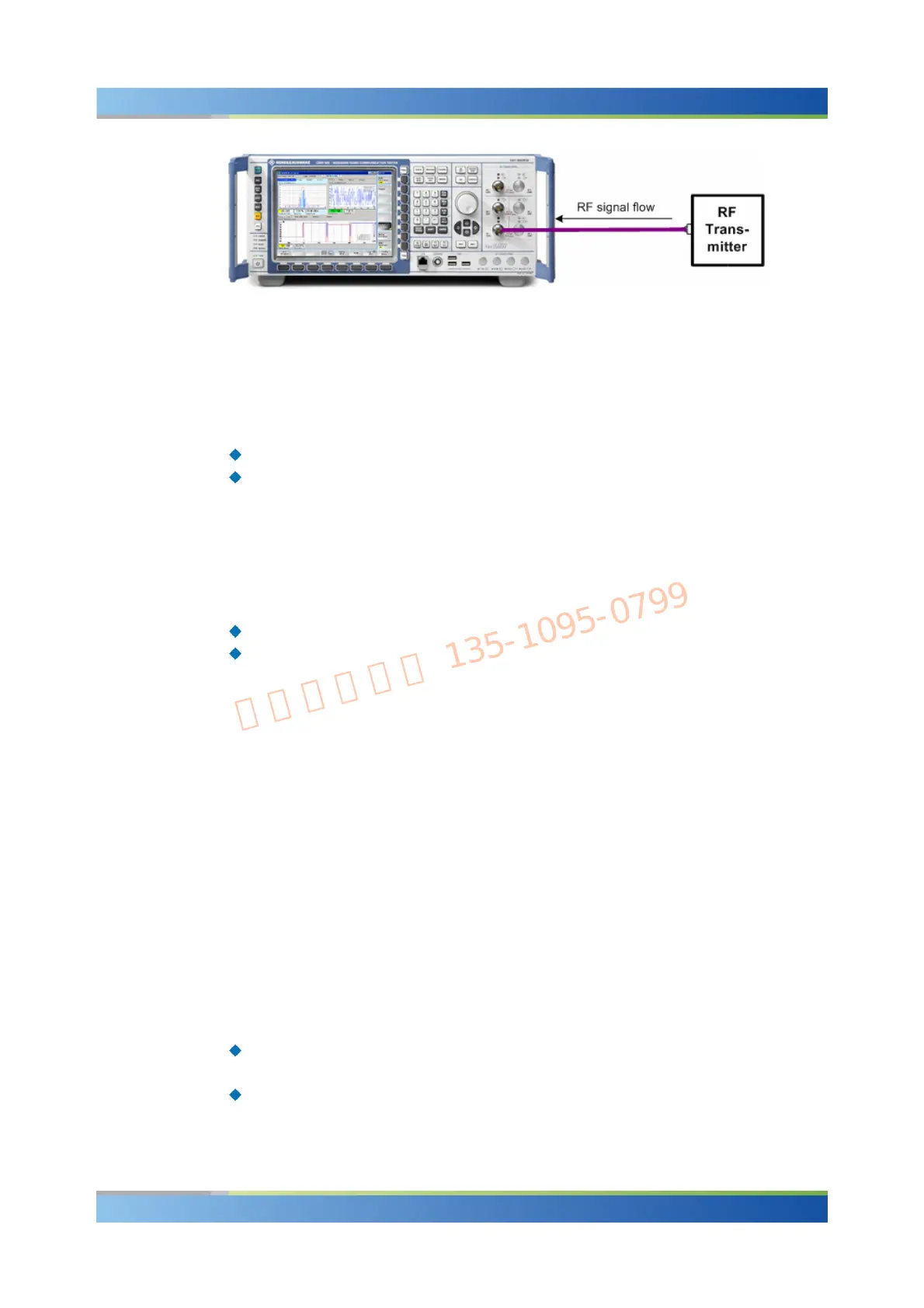
9.1.1.2 How to Measure an Uplink WCDMA Signal
After connecting your WCDMA UE to the R&S CMW 500 as shown above, you have to
adjust the following analyzer settings to the properties of the analyzed UL
WCDMA signal:
The analyzer "Frequency"
The "Expected Nominal Power" and (optional) a "User Margin" and "External
Attenuation". Recommended values: "Expected Nominal Power" = peak power of
the UE signal over the entire measurement range; "User Margin" = 0 dB (the
smallest possible value ensures maximum dynamic range).
For synchronization to the received signal and proper decoding, the "UE Signal Info"
settings in the configuration menu must be in accordance with the measured signal. In
particular, ensure that the following parameters match up:
The "Scrambling Code" and the "UL DPCCH Slot Format"
The information whether the UL signal contains a single DPCCH or a DPCCH plus
a DPDCH ("UL DPDCH Available").
The R&S CMW 500 can auto-detect the spreading factor of the DPDCH and the
corresponding symbol rate.
With matching "UE Signal Info" settings, the R&S CMW 500 is able to decode the
WCDMA UL signal and determine its slot timing. No additional measurement trigger is
required. Non-matching "UE Signal Info" settings generally result in large EVM results.
9.1.1.3 Defining the Scope of the Measurement
The WCDMA "Multi Evaluation" measurement is a multislot application: The R&S
CMW 500 can measure up to 120 consecutive WCDMA slots (8 frames) in a single
measurement cycle and store the measurement results for each slot. The total number
n of slots per measurement cycle is termed the "Measurement Length" (slots no. 0 to n
– 1).
Within this measurement interval, two individual slots are selected for a more detailed
analysis:
The "Preappointed Slot" is used to measure the Adjacent Channel Leakage power
Ratio (ACLR)and the spectrum emissions.
The "Slot Number (Table)" is used to draw up a statistics of the modulation and
code domain power results. Statistical results are relevant in particular if the
"Measurement Length" is measured repeatedly; see Statistical Settings .

 Loading...


