R&S
®
CMW 500 System Overview
Generators
Operating Manual 1202.3986.32 – 03 37
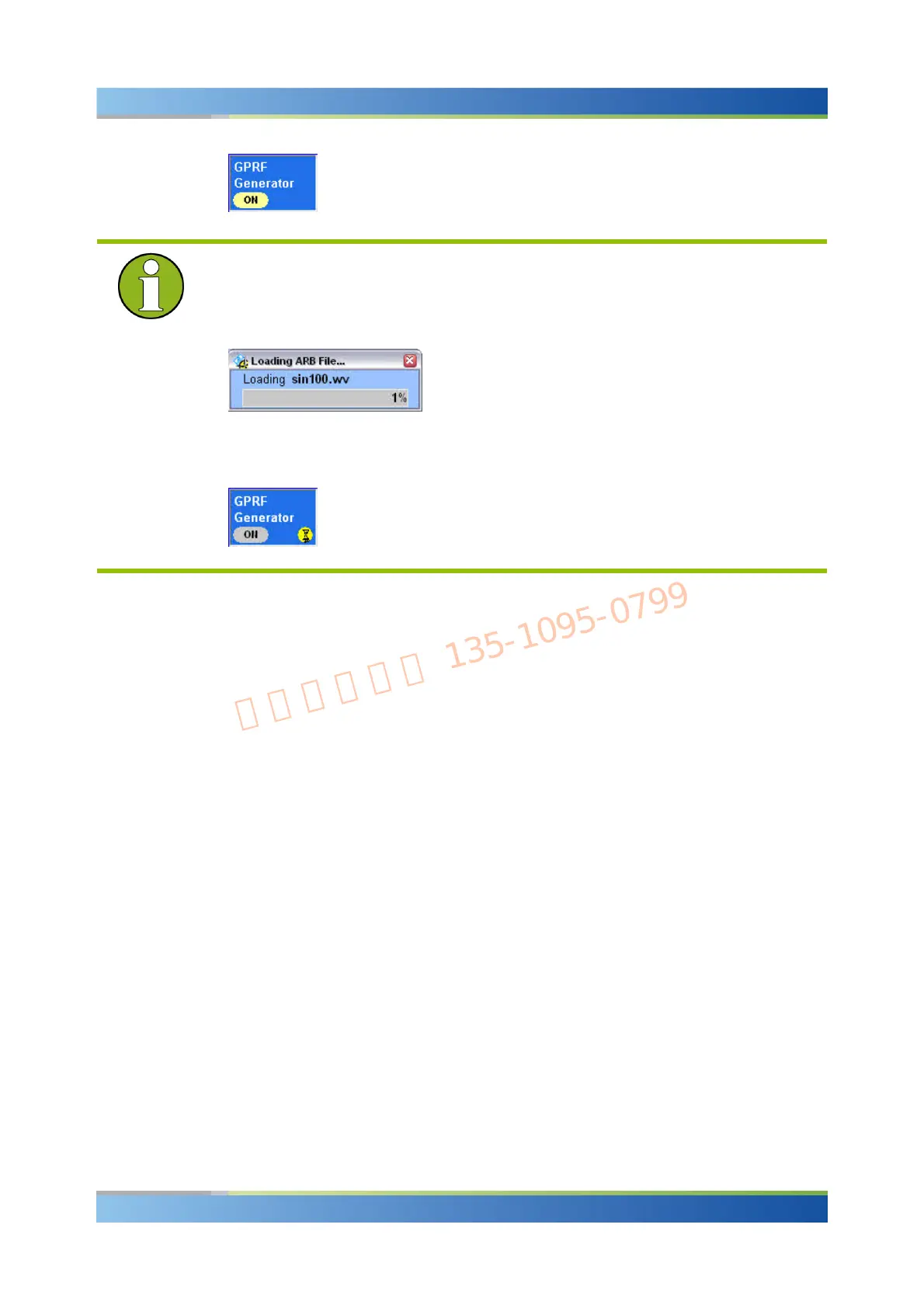
"Generator pending" state
Depending on the generator type and configuration, the R&S CMW 500 may require
some time to provide the generator signal. E.g. the ARB generator signal is available
only after a waveform file has been loaded:
While the generator is turned on but still waiting for resource allocation, adjustment,
hardware switching, a yellow sandglass symbol in the generator control softkey
indicates the "generator pending" state.
The yellow symbol disappears as soon as the generator signal is available.
3.1.2 RF Path Settings (Generators)
The R&S CMW 500 provides a number of settings that are very similar in different
generators but can be configured independently. These settings control the routing of
signals and the correction of the generator level.
Connector selection (input/output)
The R&S CMW 500 provides RF input and output connectors for different power
ranges.
The RF connector is selected in the "RF Routing" section at the beginning of the
measurement and generator configuration dialogs.
External attenuation (output)
Defines the value of an external attenuation (or gain, if the value is negative) in the
output path. This is suitable if the RF generator is to compensate for the effect of a
frequency-independent attenuating component (e.g. a cable) that is included in the test
setup.
With an external attenuation of x dB, the generator power is increased by x dB so that
the actual generator power differs from the output power shown in the dialog. The
output power in the dialog is available at the input of the DUT. Negative values of the
external attenuation decrease the effective generator power.

 Loading...


