System Overview
R&S
®
CMW500
74User Manual 1173.9463.02 ─ 06
network connection. With an established connection, the R&S CMW500 can exchange
control messages with the mobile, request the mobile capabilities, and perform various
TX and RX tests.
The R&S CMW500 supports signaling applications for various network standards. The
applications are similar in structure, however, the details of connection setup, the sig-
naling parameters, and the measurements which you can perform with an established
network connection depend on the standards. The following topics describe common
features of the signaling applications.
For a sample session refer to chapter 2.3.3, "Performing Signaling Measurements",
on page 31.
3.3.1 RF Path Settings
The R&S CMW500 provides a number of settings that are very similar in different sig-
naling applications but can be configured independently. These settings control the rout-
ing of signals and the signal levels.
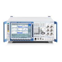
The R&S CMW500 provides various RF connectors at the front panel. The standard test
setup uses a bidirectional connection between the mobile under test and one of the bidir-
ectional (COM) connectors of the R&S CMW500.
The RF connectors and other basic signal settings are configured in the "RF Settings"
section at the beginning of the configuration dialogs. In contrast to generator or (TX)
measurement applications, signaling applications provide output and input signal set-
tings.
The RF settings are analogous to the settings in the generator applications (output) and
measurement applications (input).
For details refer to:
● chapter 3.1.2, "RF Path Settings (Generators)", on page 52
● chapter 3.2.2, "Connection Control (Measurements)", on page 54
3.3.2 Control of the Cell State
A downlink signal generator can be in the "ON", "OFF" or "RDY" state. In the default
configuration, all signaling generators are switched off; no cell signals are available. The
cell state is shown in the signaling control softkey.
Signaling Applications

 Loading...


