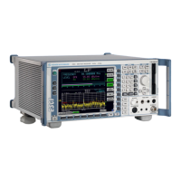
R&S ESCI Getting Started with the Instrument
1166.6004.12 1.15 E-1
ON/STANDBY switch on the front panel
ON STANDBY
Standby switch
The ON/STANDBY switch activates two different operating
modes indicated by coloured LEDs:
Operation ON - ON/STANDBY is depressed
The green LED (ON) is illuminated. The instrument is
ready for operation. All modules within the instrument are
supplied with power.
Caution:
In standby mode, the AC
power voltage is present
within the instrument
STANDBY - ON/STANDBY switch is not pressed.
The yellow LED (STANDBY) is illuminated. Only the
power supply is supplied with power and the quartz oven
is maintained at normal operating temperature.
Switching On the Instrument
! In order to switch on the R&S ESCI, set the power switch on the rear panel to position I.
! Set the R&S ESCI to operating mode by pressing the ON/STANDBY key on the front panel. The
green LED must be illuminated.
Startup Menu and Booting
After switching on the instrument, a message indicating the installed BIOS version (e.g. Analyzer BIOS
Rev. 1.2) appears on the screen for a few seconds.
Subsequently Windows XP is booted first and after that the instrument firmware will boot. As soon as
the boot process is finished the instrument will start measuring. The settings used will be the one that
was active when the instrument was previously switched off, provided no other device configuration than
FACTORY had been selected with STARTUP RECALL in the FILE menu.
Switching Off the R&S ESCI
! Switch the ON/STANDBY key on the front panel to standby mode by pressing it once.
The R&S ESCI will write the current instrument settings to disk before performing a Windows XP
shutdown. At the end of the shutdown procedure the power supply will be switched to STANDBY
mode.
The yellow LED must be illuminated.
Only when removing the R&S ESCI completely from the AC power source:
! Set the power switch at the rear panel to position 0.

 Loading...