Interfaces and Connectors
R&S
®
ETL
18Getting Started 2118.4130.02 ─ 04
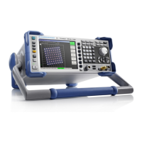
9 = GEN OUT 50 Ω output
10 = USB interfaces
11 = AF OUT output
12 = RF IN 75 Ω input
13 = RF IN 50 Ω input
14 = Display
5.1.1 ON/STANDBY Key
See (1) in Figure 5-1.
The [ON/STANDBY] key works only if the AC power switch on the back of the
R&S ETL is switched on. It switches the R&S ETL from standby to on and back.
For details on switching on or off and the instrument states, refer to Chapter 7, "Switch-
ing On or Off the Instrument", on page 41.
5.1.2 Keys for Frequently-Used Functions
See (2) in Figure 5-1.
These basic functions are provided independently from the selected measurement
mode.
For detailed information, see the user manual or the help.
PRESET key
Sets a defined instrument state.
FILE key
Displays the softkeys of the file menu used for:
●
Storing/loading instrument settings.
●
Managing stored files.
SETUP key
Displays the softkeys of the setup menu used for basic instrument configuration:
●
Frequency reference (ext/int), noise source, video/IF output (Additional Interfaces
option, R&S FSL-B5), transducer factors
●
Date, time, display configuration
●
LAN interface, remote control (GPIB Interface option, R&S FSL-B10)
●
Self-alignment
●
Firmware update and enabling of options
●
Information about instrument configuration incl. firmware version and system error
messages
●
Service support functions, for example self-test
Front Panel

 Loading...


