Interfaces and Connectors
R&S
®
ETL
25Getting Started 2118.4130.02 ─ 04
Danger of injuries
If the volume is turned up fully, you may damage your hearing.
Before putting on the headphones, check the volume setting (output voltage) carefully
using the marker menu or the [MENU] key.
This connector cannot be used simultaneously to the IF/Video output connector on the
rear panel.
5.1.12 RF IN 75 Ω Input (B203 Option)
See (12) in Figure 5-1.
Optional AC-coupled RF input with 75 Ω impedance. Male F connector.
Risk of instrument damage
Do not overload the input. See the data sheet for the limits of the input DC voltage and
the maximum continuous power at the RF input. Do not exceed these limits. Exceeding
these limits can cause instrument damage.
5.1.13 RF IN 50 Ω Input
See (13) in Figure 5-1.
AC-coupled RF input with 50 Ω impedance. Female N connector.
Risk of instrument damage
Do not overload the input. See the data sheet for the limits of the input DC voltage and
the maximum continuous power at the RF input. Do not exceed these limits. Exceeding
these limits can cause instrument damage.
When connecting the DUT, do not exceed a maximum torque of 60 Ncm. A higher tor-
que may destroy the mating components.
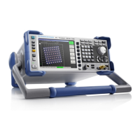
5.1.14 Display
See (14) in Figure 5-1.
Screen displaying the graphical user interface.
Front Panel

 Loading...


