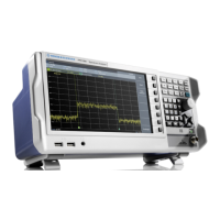
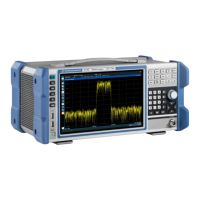
Instrument Tour
R&S
®
FPL1000
42Getting Started 1323.1602.02 ─ 07
2
1
14 15
4
6
138
3
10
9
11
16
5
7
12
Figure 5-3: Rear panel view
1+2 = Removable, rechargeable Li-Ion battery packs
3 = DC power connector
4 = AC power supply connection and main power switch with fuse
5 = GPIB (IEC 625) interface
6 = Reference clock connectors
7 = Trigger input connector
8 = "DVI" connector for external display
9 = "LAN" connector
10 = "USB" (3.0) connectors
11 = NRP power Sensor connector *)
12 = Headphones connector *)
13 = Aux. Port *)
14 = "IF/VIDEO OUT" connector *)
15 = NOISE SOURCE CONTROL *)
16 = Device ID with serial number and other labels
*) requires the "Additional Interfaces" option R&S FPL1-B5.
The meanings of the labels on the R&S FPL1000 are described in Chap-
ter 1.2, "Labels on R&S FPL1000", on page 11.
5.2.1 Li-Ion Battery Packs and DC Power Connector
With the Li-Ion battery pack (option R&S FPL1-B31), the R&S FPL1000 can be
operated independently of an AC or DC power supply. The instrument can house
2 Li-Ion battery packs which can be charged both via AC or DC power supply.
Rear Panel View
 Loading...