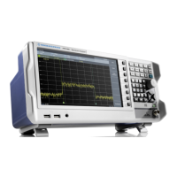
Instrument Tour
R&S
®
FPL1000
46Getting Started 1323.1602.02 ─ 07
13 1
14
25
Short-circuit hazard
Always observe the designated pin assignment. A short-circuit can damage
the port.
Table 5-4: Pin assignment for optional AUX port
Pin Signal Description
1 GND Ground
2
not used for spectrum analysis
3 GND Ground
4
not used for spectrum analysis
5 GND Ground
6
not used for spectrum analysis
7 GND Ground
8 to 11
not used for spectrum analysis
12 GND Ground
13 +5 V / max. 250 mA Supply voltage for external circuits
14 to 19 I/O_<no.> Control lines for user ports (see user manual)
20 GND Ground
21 READY FOR TRIG-
GER
Signal indicating that the instrument is ready to receive a
trigger signal.
The signal polarity is configurable.
(See the R&S FPL1000 user manual.)
22 to 25
not used for spectrum analysis
23 GND Ground
24 to 25
not used for spectrum analysis
Rear Panel View

 Loading...


