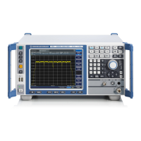
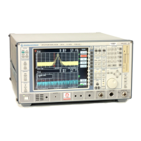
Front and Rear Panel View
R&S
®
FSVA/FSV
27Quick Start Guide 1321.3066.02 ─ 06
Position O: The entire instrument is disconnected from the AC power supply.
For details refer to Chapter 4.1.8, "Switching the Instrument On and Off",
on page 42.
Warm-up time for OCXO
When the instrument is switched on, the OCXO requires an extended
warm-up time (see data sheet).
3.2.1.2 LAN
The LAN interface can be used to connect the R&S FSVA/FSV to a local network
for remote control, printouts and data transfer. The assignment of the RJ-45 con-
nector supports twisted-pair category 5 UTP/STP cables in a star configuration
(UTP stands for unshielded twisted pair, and STP for shielded twisted pair).
3.2.1.3 MONITOR (VGA)
The female VGA connector is used to connect an external monitor. Step-by-step
instructions how to connect an external monitor are provided in Chapter 4.3,
"Connecting an External Monitor", on page 46.
3.2.1.4 EXT TRIGGER / GATE IN
The female connector for external trigger/gate input is used to control the mea-
surement by means of an external signal. The voltage levels can range from 0.5
to 3.5 V. The default value is 1.4 V. The typical input impedance is 10 kΩ.
3.2.1.5 REF IN
As a reference signal, you can either use the internal reference, or connect an
external one. The setup menu is used to switch between the internal and an
external reference. The REF IN female connector is used as an input for a 1-20
MHz reference signal. The required input level is 0-10 dBm.
Rear Panel View

 Loading...


