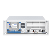
Power Amplifier - Function R&S M3SR Series 4100 HF Transceivers
1.19 6124.9007.82.01
¾ Temperature sensing TSFS
¾ Current sensing CSFS
¾ Drain / source voltage sensing signal VSFS
¾ Stable reference voltage VREF
Harmonic Filter
The signal from the Final Stage is routed via one of the eight lowpass filters to a directional coupler.
The low pass filters cover the frequency ranges 1.5 to 2.2
MHz, 2.2 to 3.2 MHz, 3.2 to 4.6 MHz, 4.6 to
6.7
MHz, 6.7 to 9.7 MHz, 9.7 to 14.2 MHz, 14.2 to 20.6 MHz and 20.6 to 30.0 MHz. The directional
coupler generates two measuring voltages FORV and REFV, which are proportional to the forward
power and reflected power, respectively. The BIT REL switch is energized only during Built-In-Test
(BIT) operation, terminating the HF signal with a 50
Ω resistor. During normal operation, the HF signal
is forwarded via a decoupling capacitor to the antenna connector X30. As soon as the signal ATU REL
is active, a 28-V DC voltage is applied via current limiting circuit and low pass filter to the antenna
output. This ensures the power supply of the antenna tuning unit, if connected.
Control Board
The Control Board controls all the other boards included in the module and implements the transmit
power regulation. The FPGA is configured via CPLD with data stored in the FLASH. The amplifier con
-
trol functions are commanded using the serial Radio Control Bus (RCB). The output to other RCB de-
vices is also available. The forward and reflected wave voltages from the directional coupler and the final
stage current are sampled by fast 10-bit A/D converters. The values are passed to the regulator, which
is implemented in the FPGA. The regulator output drives the 14-bit D/A converter. Its analog output is
routed through a low pass filter to the attenuator driver. For storage of the power calibration values a
FRAM memory is available. The Control Board permanently monitors the supply voltages and the final
stage temperature.
DC Power Supply
From an external DC voltage the DC Power Supply generates all voltages needed for operating the
radio and driving the fans. Connector X31 is the main input (28
VDC, ≤ 25 A) and X32 is the battery
input (19 to 31
VDC, ≤ 25 A). Connectors X320 (External supply) and X321 (Control) are connected to
the Motherboard. The DC Power Supply is fitted with a Built-in Test Equipment.

 Loading...