Instrument Tour
R&S
®
RTO
19Getting Started 1316.0833.02 ─ 10
3 Instrument Tour
This chapter describes the front and rear panels of the instrument including all function
keys and connectors, and also the touchscreen with its control elements.
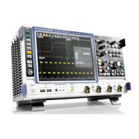
3.1 Front Panel
The front panel of the R&S RTO is shown in figure 3-1. The function keys are grouped
in functional blocks to the left and the right of the touchscreen. Below, various connec-
tors are located.
Fig. 3-1: Front panel of R&S
RTO1024 with 4 input channels
1 = Touchscreen
2 = SETUP controls
3 = HORIZONTAL controls
4 = TRIGGER controls
5 = ANALYSIS controls
6 = VERTICAL controls
7 = NAVIGATION controls
8 = POWER key
9 = Connectors for USB and probe compensation
10 = Input channels
Front Panel
 Loading...


