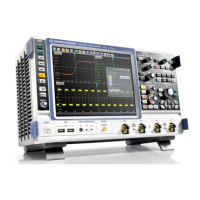
Instrument Tour
R&S
®
RTO
33Getting Started 1316.0833.02 ─ 10
AC power supply connector and main power switch
Connection to the AC power line. The R&S RTO can be used with different AC power
voltages and adapts itself automatically to it. The nominal voltage and frequencies
ranges are displayed on the rear panel and quoted in the data sheet.
If grounding is not ensured by the mains system, ground the instrument using the pro-
tective earth conductor on the front panel and an appropriate cable.
The AC main power switch also interrupts the power supply of the OCXO (option
OCXO Reference Frequency, R&S RTO-B4).
When you power up the instrument, be sure to comply with the warm-up phase speci-
fied in the data sheet before you start measurements.
See also: chapter 2.3, "Starting the Instrument", on page 14
USB
Two USB type A connectors that comply with standard USB 2.0. They are used to con-
nect devices like keyboard, mouse, printer and flash drive to store and reload instru-
ment settings and measurement data. Also environment sensors can be connected to
measure and display temperature and other environment conditions.
Note: Electromagnetic interference (EMI) can affect the measurement results. To
avoid any impact, do not use USB connecting cables exceeding 1 m in length.
LAN
8-pin RJ-45 connector used to connect the instrument to a Local Area Network (LAN).
It supports up to 1000 Mbit/s (10/100/1000BASE-T Ethernet).
MONITOR (DVI-D)
Digital connector for an external monitor or projector. The monitor shows the complete
content of the instrument's screen.
See also: chapter 2.4.2, "Connecting an External Monitor", on page 17.
EXT TRIGGER INPUT
The BNC connector for external trigger input is used to control the measurement by
means of an external signal. The input impedance can be selected in the trigger config-
uration, the values are 50 Ω and 1 MΩ. The trigger level can be set from -5 V to 5 V.
The maximum input voltage is 30 V RMS at 1 MΩ input impedance and 7 V RMS at
50 Ω input impedance.
EXT TRIGGER OUTPUT
The BNC connector for external trigger output is used to provide the internal trigger
signal of the oscilloscope to trigger other instruments for synchronized measurements.
When a trigger occurs, the R&S RTO creates a pulse of 5 V with a source impedance
of 50 Ω and delivers it to the external trigger output. The instrument can also send the
pulse on mask test violation or violation of measurement limits and margins.
If the connector is terminated with 50 Ω, the signal level is 2.5 V (50 mA), and with
1 MΩ termination the level is 5 V. A short-circuit of the connector to ground creates
current of 100 mA.
Rear Panel
 Loading...


