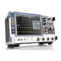
Instrument Tour
R&S
®
RTO
34Getting Started 1316.0833.02 ─ 10
To enable the trigger out signal, select "Trigger" menu > "Trigger Control". Here you
also adjust polarity, delay, and length of the pulse. The default is a positive pulse of
100 ns. The minimum delay is 800 ns.
RTO-B1 (MSO)
Mixed Signal Option, input for digital signals (parallel buses). The hardware module
and digital probe come with option R&S RTO-B1. The module provides connectors for
two logical probes with 8 digital channels each (D0 to D7 and D8 to D15).
The maximum input voltage is 40 V peak at 100 kΩ input impedance. The maximum
input frequency for a signal with the minimum input voltage swing of 500 mV (V
pp
) is
400 MHz. For detailed specifications refer to the Data Sheet.
RTO-B10 (GBIP)
Optional GBIP connector coming with option R&S RTO-B10 GBIP Interface. For
detailed specifications refer to the Data Sheet.
RTO-B4 (OCXO), REF IN AND REF OUT
Optional REF IN (left) and REF OUT (right) connectors coming with option
R&S RTOB4 OCXO 10 MHz.
The input frequency ranges from 1 MHz to 20 MHz in 1 MHz steps. The input impe-
dance is 50 Ω.
The output frequency of the OCXO is 10 MHz, the impedance is 50 Ω. For detailed
specifications refer to the Data Sheet.
Rear Panel

 Loading...


