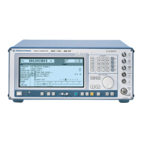
Arbitrary Waveform Generator ARB SMIQ
1125.5555.03 E-92.342
This conception has been considerably improved in the option SMIQB60. The modulation signal is
interpolated to a higher sampling rate by means of a very steep-edged, digital interpolation filter and is
then output. The interpolation rate is set by the SMIQB60 automatically such that aliasing of the
interpolated sampling rate is suppressed by the analog filter. This procedure offers the following
advantages to the user:
1. Oversampling has to be selected such that the bandwidth of the interpolation filter exceeds that of
the modulation signal. The following equation applies:
ov * int_bw >= mod_bw,
ov == Oversampling,
int_bw == 0.375, standardized bandwidth of the interpolation filter,
mod_bw == bandwidth of the modulation signal standardized to symbol rate
The following value is thus obtained for the digital standard W-CDMA with the baseband filter √cos,
α = 0.22:
mod_bw =
2
α)(1+
++
+
= 0.61, => ov >=
0.375
0.61
= 1.63.
2. Due to the reduced oversampling, the duration of the signal increases with constant number of
sampling values. Accordingly, the number of sampling values decreases with constant signal
duration. Usually, with conventional ARB generators, the minimum oversampling is limited to 4. Thus,
provided that the above parameters of the W-CDMA system apply, the 512 ksamples of the SMIQB60
correspond to 4/1.63 * 512 = 1256 kSamples memory in a conventional ARB generator.
The block diagram in Fig. 2-215 roughly illustrates the structure of the ARB generator.
FLASH RAM
1.5MSamples
Waveform RAM
512kSamples
DSP
D/A
Converter
Filter
45kHz, 12MHz
Out put
Ampli fier
Interpolator
up
I_OUT
i_MOD
D/A
Converter
Filter
45kHz, 12MHz
Out put
Ampl i f ier
Interpolator
up
Q_OUT
Q_ MOD
Trigger Unit
TRIGOUT_2
TRIGOUT_1
32
24
12
12
14
14
DATA IN
Clock
Synthesiz er
up*clock
TRIGGER IN
Fig. 2-215 Block diagram SMIQB60

 Loading...