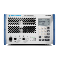
R&S SU 4200 Interface Description
6125.0226.12.01 6.8
Entry in column D (direction): O = Output I = Input B = Bi-directional
Entry in column T (type): A = Analog D = Digital P = Power
Signal description D T Range Contact Remarks
SER_CONTR_TXD_B O D X7.11
SER_CONTR_RXD_A I D X7.12
SER_CONTR_RXD_B I D
Ri = 120 (a−b)
Max. ±6.8 V
against Gnd
X7.13
interface for remote
control or interface to
external motor tuned
Telsa filter
USER_OUT O D Low = active
Ri = 220
limited to max. 6.8 V
CMOS 3.3 V
X7.14
USER_IN I D Contact against
Gnd = active
Internal pull-up 10 k
to 3.3 V, limited to
max. 6.8 V
X7.15
RX Input X8\RX Input X8 "Radio ".doc
Ethernet – LAN Remote Control X9\Ethernet – LAN Remote Control X9 "Radio".doc
RX Audio Basic X10\RX Audio Basic X10 "Radio".doc
RX Audio Exte nded X11\ RX Audio Extende d X11 "Radio".do c
Host Interface Port X12\Host Interface Port X12 "Radio".doc
6.2.8 RS-422 – Host Interface Port X12 (Reserved)
RS-422 − Host interface port (EIA-530/LAPB)
DCE configurated – DSUB female (25pins)
Fig. 6.8 RS-422 – Host interface port X12 (reserved)
ATTENTION
Reserved connector.
Do not connect any signal to connector X12.
The radio may be damaged if any signal is connected.
Communication Data Connector X13\Communication Data Connector X13 "Radio".doc
Communication Data Connector X14\Communication Data Connector X14 "Radio".doc

 Loading...