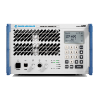
Index R&S SU 4200
7.1 6125.0226.12.01
Last Page of Chapter 6\\Last Page of Chapter 6 "Radio".doc
7 Index
7.1 Index
A
AC
LED ...............................................................3.24
ACARS ..............................................................3.61
Accessories ........................................................ 1.6
ACTIV (display).........................................3.21, 3.28
Activation ...........................................................3.53
Activation (menu)...............................................3.28
ACTive device ...................................................3.53
AM (display).......................................................3.21
Application .......................................................... 1.1
Auto (Activation) ................................................3.53
B
Basis cabling ...................................................... 2.5
Blank panel...................................................2.3, 2.4
Block Diagram .................................................... 1.4
Boot display .......................................................3.20
Brightness..........................................................3.23
C
Cabling
Front............................................................... 2.8
CARR (LED) ......................................................3.24
CBIT state........................................................... 4.4
CBIT STATUS
Display ..........................................................3.21
Menu .............................................................3.40
CBIT type configuration .....................................3.15
Check
Cabling ........................................................... 4.1
CBIT state ...................................................... 4.3
LED state ....................................................... 4.2
Checking (Unit) ................................................... 2.2
Configuration (Main/Standby) ............................3.53
CONFIGURATION (menu) ................................3.43
Configuring ......................................................... 3.8
Connectors ......................................................... 6.1
Contrast .............................................................3.23
Control
Front view....................................................... 3.2
Mode .............................................................. 3.5
Rear view ....................................................... 3.3
Control elements................................................. 3.2
Cursor keys (description)...................................3.17
D
DC
LED ...............................................................3.24
Default, instrument settings ................................ 3.8
Design ................................................................ 1.3
Device 1.............................................................3.53
Device 2.............................................................3.53
Device Main.......................................................3.53
Device Standby .................................................3.53
Display...............................................................3.20
Boot...............................................................3.20
Main menu ....................................................3.22
Standard operating display ...........................3.21
Display Settings.................................................3.23
E
Enable SNMP....................................................3.13
ENTER key (description) ...................................3.18
Entry ..................................................................3.17
Entering numerical parameters .....................3.30
Selection .......................................................3.29
Toggling ........................................................3.28
Errors...................................................................4.4
ESC key (description)........................................3.18
Explanation..........................................................1.1
EXTERNAL VOLTAGES (menu).......................3.38
F
Features ..............................................................1.1
Fixed session.......................................................3.6
Frequency (setting)............................................3.30
FREQUENCY BLOCK (menu)...........................3.46
Front
Cabling............................................................2.8
View ................................................................3.2
Function
Description (structure).....................................1.5
Keys (assignment) ........................................3.31
Test ...............................................................2.10
G
GB2PP Commands ...........................................6.11
General data........................................................1.6
GO (LED) ..........................................................3.24
H
Headset (connection) ..........................................2.8
I
INACTIV (display).....................................3.21, 3.28
INACTive device................................................3.53
In-Band..............................................................3.60
In-Band signaling...............................................3.60
Index....................................................................7.1
Indication via LEDs............................................3.24
Inputs...................................................................6.1
Inspection
Cabling............................................................4.1
CBIT state .......................................................4.3
LED state ........................................................4.2
Installation
Blank panel ..............................................2.3, 2.4
Instrument
Functions.......................................................3.31
Settings (factory) .............................................3.8
Interface description
Mechanical ......................................................2.9
Interfaces.............................................................6.1
INVENTORY (menu) .........................................3.41
IP-ADDRESS (menu) ...............................3.44, 3.45

 Loading...