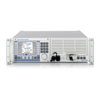
6 Digital Reprogrammable Software Radios R&S M3SR
Specifications for basic fixed-frequency radio
Common data for transmitter, transceiver and receiver radio
configurations
Unless stated otherwise, specs are valid for the frequency range from 108 MHz
to 174 MHz and 225 MHz to 400 MHz. For the remaining ranges down to
100 MHz and up to 512 MHz, minor deviations may occur.
Usable frequency range 100 MHz to 512 MHz without gap
Waveforms contained in
standard radio configuration
VHF (108 MHz to 173.975 MHz):
LOS FM
LOS AM
Civil ATC AM acc. to EN300676
UHF (225 MHz to 399.975 MHz):
LOS FM
LOS AM
Optional waveforms – HAVE QUICK I/II acc. to STANAG4246
– SATURN acc. to STANAG4372
– UHF DAMA with external modem
acc. to MIL-STD-188-181/2/3 on
request
– Link 11 with external modem acc. to
STANAG5511
– Link 22 with external modem acc. to
STANAG5522 on request
– Link 4A with external modem acc. to
STANAG5504 on request
– Link Y Mk2 with external modem on
request
– SECOS voice, Rohde&Schwarz
TRANSEC/COMSEC waveform
– SECOS with data preprocessor (DPP)
– SECOS with TDMA on request
– other waveforms on request
Channel spacing 8.33 kHz, 25 kHz, 75 kHz (HAVE QUICK
mode)
Frequency spacing 8.33 kHz, 12.5 kHz and 25 kHz synthe-
sizer increments
Frequency drift (–20qC to +55qC) 0.1 ppm (10
–7
) with OCXO
Frequency offset (for TX only) up to 4-carrier offset mode ±2.5 kHz/
5 kHz/7.5 kHz
5-carrier offset mode on request
Preset pages (channel configuration,
including all operational parameters)
200
Classes of emission AM: A3E, A9E, AXX (16 kbit/s base-
band and diphase)
FM: F3E, F9E, FSK, FSK-MSK
Receiver data
Sensitivity
With AM (m = 0.3)
With FM (±3.5 kHz deviation)
For (S+N)/N = 10 dB (weighted to
ITU-T) and f
m
= 1 kHz
d–107 dBm (low-noise mode)
d–101 dBm (low-distortion mode)
d–110 dBm (low-noise mode)
d–104 dBm (low-distortion mode)
Note: If a guard receiver with common main receiver antenna is installed in an
R&S M3SR, the sensitivity of the main receiver is reduced by 4 dB.
AM internal noise level
(with input signal –47 dBm,
f
m
= 1 kHz, m = 0.3) (S+N)/N t40 dB (modulated-to-
unmodulated), weighted to ITU-T
FM noise quieting (with input signal
–70 dBm, f
m
= 1 kHz;
deviation = ±3.5 kHz )
(S+N)/N t40 dB, weighted to ITU-T
Selectivity (IF bandwidth)
Main RX
BW 1 for 25 kHz channel spacing
BW 2 for 8.33 kHz channel spacing
BW 3 for data
BW 4 for data
t26 kHz/6 dB, d50 kHz/80 dB
t7 kHz/6 dB, d13 kHz/60 dB
t50 kHz/6 dB, d150 kHz/70 dB
t70 kHz/6 dB, d140 kHz/60 dB
RFI (radio frequency interference) suppression
Adjacent-channel rejection VHF ATC band acc. to EN300676
t60 dB for 8.33 kHz and 25 kHz channel
spacing
Desensitization
S+N/N !10 dB, weighted to ITU-T
wanted signal –95 dBm/m = 0.6,
unwanted signal +80 dBc
VHF at !±200 kHz
UHF at !±200 kHz
IF/image rejection t80 dB
Spurious rejection 80 dB
Suppression of 3rd order intermodula-
tion products
Low-distortion mode, ref = –101 dBm,
m = 30%, 'f = 100 kHz
t70 dB
Local oscillator reradiation at antenna
connector
d–90 dBm
Squelch
(S+N)/N setting range 6 dB to 20 dB
Squelch hysteresis 1.5 dB to 6 dB
Squelch attenuation (muting) (AF out-
put with activated squelch threshold)
d–70 dBm
AF outputs (voice) (valid for A3E and F3E in plain and fixed-frequency mode)
Line output
Impedance
Level with input signal –47 dBm,
f
m
= 1 kHz, m = 0.6 or 'f = 3.5 kHz
600 : ±10%
0 dBm nominal (–20 dBm to +10 dBm
settable) into 600 :, balanced (float-
ing) allowing external grounding;
500 V minimum isolation against
ground
AF response
With 25 kHz channel spacing and
input signal –47 dBm, m = 0.3
With 8.33 kHz channel spacing and
input signal –47 dBm, m = 0.3
300 Hz to 3500 Hz with ±2 dB
d150 Hz with d–15 dB (f
ref
= 1 kHz)
t5000 Hz with d–20 dB (f
ref
= 1 kHz)
300 Hz to 3000 Hz with ±2 dB
d150 Hz with d–15 dB (f
ref
= 1 kHz)
t4000 Hz with d–20 dB (f
ref
= 1 kHz)
THD (total harmonic distortion)
(with input signal –79 dBm to +3 dBm,
f
m
= 1 kHz and 600 : termination)
With m = 0.6
With m = 0.9
d5%
d10%
Noise peak limiter threshold range m = 0.3 to 0.9 adjustable
AF AGC with input variation
m = 0.3 to 0.9
d1 dB AF output variation

 Loading...