Do you have a question about the Roland Boss RC-20XL and is the answer not in the manual?
| Type | Loop Station |
|---|---|
| Recording Time | 16 minutes (mono) |
| Number of Loops | 1 |
| Power | 9V DC adapter |
| Outputs | 1/4" output |
Describes how user data is preserved or deleted after certain operations.
Covers power, dimensions, weight, accessories, and options.
Describes controls, indicators, and connectors.
Explains limitations on supplying parts as service parts.
Details nominal input/output levels and impedance characteristics.
Specifies internal memory capacity and recording duration.
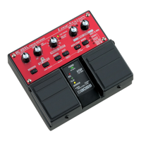
Illustrates the front panel with numbered controls for identification.
Lists and briefly describes each control element shown on the panel.
Detailed list of part codes, names, descriptions, and quantities for controls.
Diagram and list of components for the first exploded view section.
Diagram and list of components for the second exploded view section.
Diagram and list of components for the third exploded view section.
Diagram and list of components for the Fig. A exploded view section.
Lists components for chassis, knobs, switches, and jacks.
Lists components for PCBs, integrated circuits, and transistors.
Lists various diodes and resistors with specifications and locations.
Lists potentiometers and capacitors with their specifications.
Lists coils, crystals, connectors, and wiring components.
Lists screws, packing materials, miscellaneous items, and accessories.
Explains how to check internal ROM and external FLASH version numbers via LEDs.
Details the steps for transmitting and receiving data between units.
Explains transmittable data types and important notes for the process.
Step-by-step guide to restore the unit to its original factory settings.
Introduces the test mode and lists general test items required.
Verifies the integrity of the FLASH ROM by checking LED indicators.
Explains how to verify internal ROM and external FLASH version numbers.
Tests the functionality of switches and LEDs using external equipment.
Verifies the LEVEL volume control's effect on output waveform.
Verifies the GUIDE volume control's effect on output waveform.
Checks DC leakage and level of the output waveform.
Verifies the output waveform with INST and MIC volumes set.
Verifies the INST volume control's effect on output waveform.
Verifies the MIC volume control's effect on output waveform.
Verifies the output waveform and noise level in mute condition.
Tests AUX IN functionality in NORMAL mode via waveform.
Tests AUX IN functionality in FLAT AMP SIMULATE mode.
Tests AUX IN functionality in CENTER CANCEL mode.
Tests AUX IN functionality with L channel input via waveform.
Verifies solder joints by checking output waveform conditions.
Measures residual noise output under various volume and drop conditions.
Illustrates the overall system architecture and component interconnections.
Shows the placement of components on the main panel circuit board.
Displays the trace layout on the foil side of the panel circuit board.
Detailed schematic showing the electrical connections of the panel board.
Shows the placement of components on the jack board circuit board.
Displays the trace layout on the foil side of the jack board circuit board.
Detailed schematic showing electrical connections for Jack 1.
Detailed schematic showing electrical connections for Jack 2.
