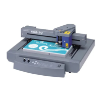
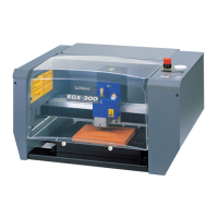
5-3 Surface Leveling of the Workpiece Table
This adjusts the atness of the surface of the workpiece table by cutting the table surface to a uniform depth. This operation
is called “surface leveling” or “surfacing.”
This can be useful in cases where rigorously precise atness is required, such as for plate engraving performed without using
the nose unit. A single surface-leveling operation takes about one hour. If uncut areas remain, perform surfacing a second
time. Also, pausing this operation while in progress is possible, just as with ordinary cutting.
P.49, “Pausing and Resuming Cutting”
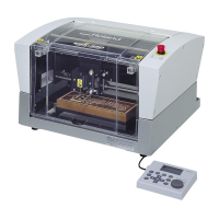
Verifying the Cutter Used and the Settings
Cutter used: Included at cutter (ZEC-A2320)
Z-axis origin point (Z0 position): Surface of the workpiece-table center
Lock-lever position:
Spindle speed: 14,000 rpm*
Cutting-in amount: 0.3 mm (invariable)
Cut-out amount: 1 mm (invariable)
Feed rate: 15 mm/sec. (invariable)
Cutting area: Entire X- and Y-axis operating range (invariable)
* The speed of spindle rotation at the time surface-leveling cutting starts is always 14,000 rpm. Watch the status of cutting
and modify this as required.
P. 48, “Adjusting the Spindle Speed,” p. 62, “Cutter Installation Method 2”
Procedure
Carry out steps
1.
and
2.
on page 62 to 63, “Cutter Installation Method 2.”
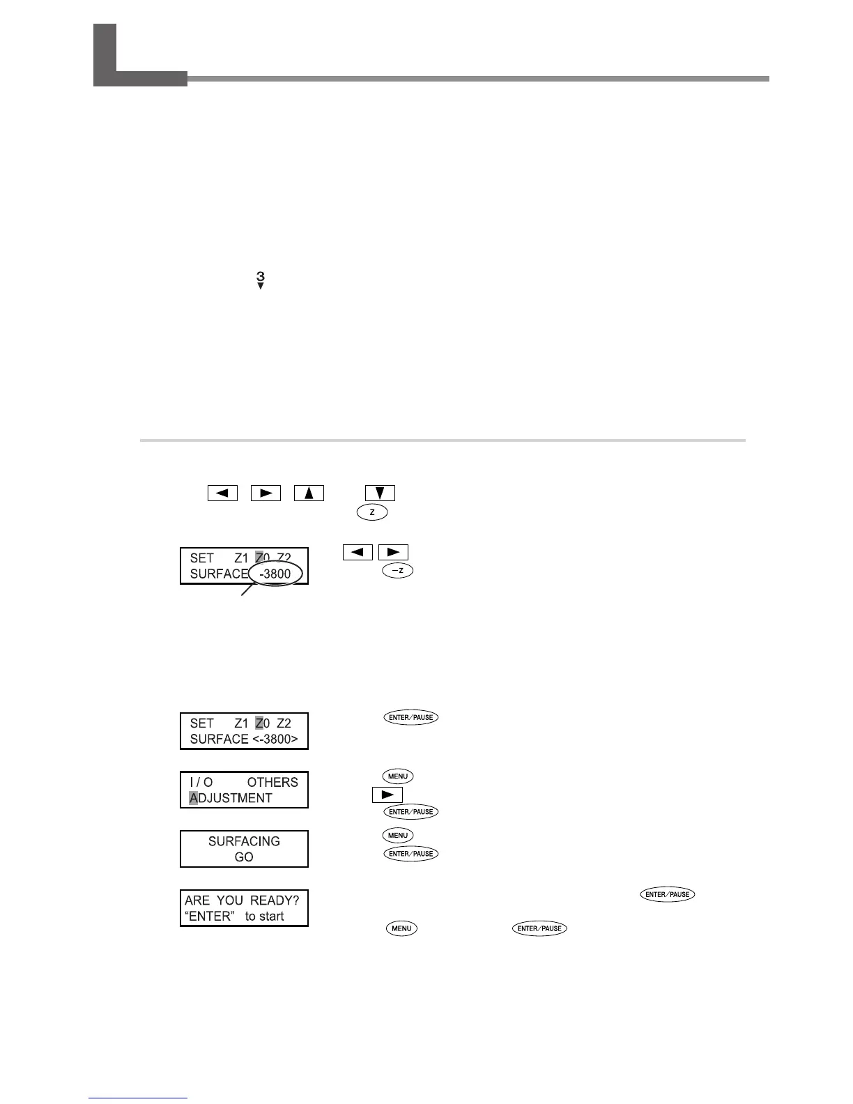
Use , , , and to move the cutter to the area above the center of the
workpiece table, then press
.
P. 44, “Manual Movement”
Use or to select [Z0].
Press
to lower the spindle head to the location where the
Zaxis
coordinate is “-3800.”
Insert a at cutter (ZEC-A2320) into the cutter holder, bring the tip of the cutter into contact
with the surface of the workpiece table, and secure the cutter in place.
For information on how to secure the cutter in place, refer to page 64 and 65.
Press to conrm.
The Z-axis coordinate is set.
Press several times to display the view shown at left.
Use
to select [ADJUSTMENT].
Press
.
Press twice.
Press
.
When the screen shown at left appears, press .
The cutting for surface leveling starts.
Pressing
before you press returns you to the screen in step
.
Check visually to ensure that no uncut areas remain.
If uncut areas are present, redo the procedure from step
.
Z-axis coordinate
83
 Loading...