The Glitch Science Roland JX-305 LCD Replacement Guide
produced by: glitchscience.com 2011©
2014©
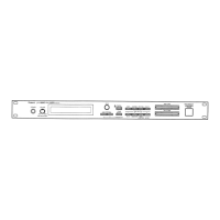
Fig. 2 - Inside the JX-305
Step 2:
You will need to remove all of the screws from the bottom of the case in order to
open it up. Once all of the screws are removed, remove the bottom cover and set
it aside.
The photo above shows the inside of the JX-305. The main board must be
removed in order to replace the LCD. To remove the main board you need to
remove the 2 screws on the top of the board and also the 7 screws from the back
of the case. You will also need to unplug the cables connected to the main board.
Be sure to make note of the orientation of the cables so that you can reassemble
it correctly when you finish the installation of the LCD.

 Loading...