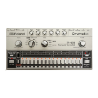
TR-808
JUN.
15,1981
ADJUSTMENT
ADJUSTMENT Connect Set Adjust Reading
CPU
CLOCK
scope
to
TP-1
IFT-1 2us/c.ycle(500kHz)
check 4V
p-p
INT
CLOCK
scope to
TP-2
TM-1
1.
9ms/cycle
TEMPO
CLOCK
scope to
TP-3
TEMPO. FINE
:FCW TM-2
8.
53ms/cycle
TEMPO: FCCW
FINE : FCW
check
65ms+5nis/cycle
NOISE
GENERATOR
AC
volt-
meter
to
TP-4
TM-4
130mV
rms
CP (HAND
CLAP)
OEESET
scope
to
TP-5
V7rite, play
CP
at a
tempo
w/
LEVEL
FCW
TM-3
CB
(COW
BELL)
FREQUENCY
scope to
TP-6
TM-1 1.85ins/cycle
TP-7
TM-2
1.
25ins/cycle
d
CHECKING
VOICES
-
Refer
to right-hand table
-
Connect scope to
the
MULTI OUT
jack
of
a
VOICE.
When observing
amplitude, set
ACCENT LEVEL
to
FCCW position
ard
the
VOICE LEVEL
to
FCW,
then
turn
ACCENT FCW.
DECAY,
TONE,
etc. for that
voice
must be
set at 12
o'clock.
iO
Vp
TROUBLESHOOTING
This
section
describes funda-
mental
approach
to isolate
defective circuits or compo-
nents .
Although
most
TR-808
circuits
function
under
the CPU
control,
possible reasons will often
be
found on peripheral
circuits.
Replace
CPU
last
of all.
Some useful information
can
be
derived
from
the
circuit
description.
AMPLITUDE
FREQUENCY
DECAY
TIME
NORMAL
ACCENT
LOW MID
HIGH SHORT
MID LONG
Vpp
Vpp
ms
(Hz)
ms
(Hz)
ms
(Hz)
ms
ms
ms
BD
3.5
10
—
18
(56)
—
50
300 800
SD
H
L
3
10
—
2.1
(476)
—
—
60
—
4.2
(238)
LC
3.5
12
6.1
(165)
5.4
(185)
4.5
(220)
—
180
—
LT 3.5
12
12.5
(80)
11.1
(90)
10
(100)
—
200
—
MC 3
10
4
(250)
3.6
(280)
3.2
(310)
—
100
—
MT
3
11
8.3
(120)
7.4
(135)
6.3
(160)
—
130
—
HC
3.5
12
2.7
(370)
2.5
(400)
2.2
(455)
—
80
—
NT
3.5 12
6.1
(165)
5.4
(185)
4.5
(220)
—
100
—
C
2.5
8
—
0.4
(2500)
—
—
25
—
RS
H
L
3
10
—
0.6
(1667)
—
—
10
—
2.2
(455)
M
3
5
—
—
—
25
—
35
CP
6
2
—
—
—
—
100
—
CB
H
L
3.5
12
—
1.25
(800)
— —
50
—
1.85
(540)
CY
3.5
7
— —
—
350
800
1200
OH 3.5
7
—
—
—
90 450
600
CH
3
6
—
—
—
—
50
—
DC
SUPPLY
Confirmation of
DC
supply voltages is the
first
thing
to
be done
in
troubleshooting. Check
+5V,
+15V
and back-up.
CPU
is forced to reset
and is
not
allowed to restart when
DC source
is
so
irregular that
Voltage
Change
Detector
keeps reset signal.
Lower impedance load
connecting
to voice output jack
can
draw relatively large current through
op
amp when the
scund level
is
high. The
sum of
the currents,
when many
louder voices
are
outputted in
step,
flowing into these
loads would cause
DC
source to drop
enough
below
the De-
tector sensing
level.
To
make sure
of this, pull all
plugs
off the
jacks. Contrast
to
the above is
a
short-
circuitting IC
.
One
short
circuit in
a stage
only could
not be sensed by the detector since
"B"
supplied to
a
particular circuit group is independently filtered, or
rather,
the short circuit will
increase
ripples in the
line,
causing TEMPO
CLOCK
to be unstable.
STATUS,
SWITCH SCANNING
Each
port at
PH
routes scanning
signal
to
the switches
connecting
to its bus.
PA
and
PB
read
signals coming via
the
switches.
If
a
switch is
misread,
check scannings
for
other switches: one
sharing the same
PH
bus, one
sharing
the
same
input
port
-
with corresponding switchings.
RAM
STORED
DATA
As
shown in memory map
on
page
A,
a
RAM
is partitioned
into
blocks.
It
is
unlikely
to
occur
in
a
RAM
that only
one
block fails to
handle
data
when the
RAM
or the
De-
coder
malfunctions. For example, if
all
instrument
data
but
Cow Bell enter IC8, similar
phenomenon
might true to
other
RAMs
, were
the troubles through
PC-0 bus.
TRIGGER
PULSE
Lack of trigger pulse from
a
gate is not
what Common
Trig
is responsible for,
when other sound generators
are
fired
.
Common Trig with pulse width longer or
shorter than
1ms
will
be
a
cause of deteriorative
voices.
values
are
typical and
variable
14

 Loading...