8
1. Entering test mode
Holding down [EDIT] and [STATUS] button on the CH5, turn on power.
The unit is now in the test mode.
2. Selection of the test from a menu
The test menu screen show the test menu A. Pressing [PARAMETER]
button [>>] cycles menus B to H and then back to A ( button [<<] in reversal
order ).
Each menu is divided into several tests .
Select the desired test option by using [PARAMETER] buttons.
Square boxes on the test screen shows the available tests in the selected
menu.
A set can be selected by pressing a button [SONG], [LOCATOR], [TRACK],
[EFFECT], [SYSTEM] or [DISPLAY] (SONG corresponds to test 1,
LOCATOR, test 2 and so forth, ).
Press the desired test select button and the selected box turns back.
The LCD shows the test name and the prompt "Rdy" .
To start the test, press the select button again.
To select a test of a different test menu, press [PARAMETER] [<<] or [>>]
button, and the desired test select button.
3. Test options
[A:LED Check]
[1:LED Scan] Turns on and then off LEDs one by one.
[2:LED Blink] Flashes all LEDs simultaneously (except 4 LEDs under
INPUT SENS).
[3:LED All On] Turns on all LEDs simultaneously (except 4 LEDs
under INPUT SENS).
[4:LED ManuScan] Turns on LEDs one by one as TIME/VALUE dial is
turned.
[B:LCD Check]
[1:LCD Black] Turns on all LCD dots simultaneously.
[2:LCD White] Turns off all LCD dots simultaneously.
[3:LCD Check1] Turns on LCD in a check pattern.
[4:LCD Check2] Turns on LCD in a check pattern but in the reverse
video of that of check 1 above.
[5:LCD Check3] Displays all ASCII character codes one by one on the
LCD.
To exit the test, press a parameter or test select button.
[C:Panel Check]
[1:Sw(Exit=Enc)] Test all switches on panel board.
Press switches except for power switch one by one.
Simultaneous pressing of two of more buttons causes
error which is indicated by flashing of all LEDs.
After testing all switches, turn TIME/VALUE dial.
the display should show "Ok!", or "Err" and the number
of switches untested or unrecognized.
[2:Encoder] Turn TIME/VALUE dial clockwise and counterclockwise
and verify corresponding readings (-25 and +25 at
extremes) on the LCD.
[3:Fader] Slide up and down the faders 1 to 8.
The LCD draws bar graphs representing setting of the
faders.
Each channel LED lights green when the fader is at the
button (0), orange at the middle (64) of the stroke and
red at the top position (127).
[4:Pan&Aux] Turn PAN knobs one by one.
The LCD increases and decreases the bar graph of the
channel as its PAN control is turned.
All the channel LEDs turn on in the color shown below
as PAN knob of a channel just reaches the following
setting.
Green at L (0), Orange at C (64), Red at R (127).
This also applies to the bar graph for the AUX SENS.
All PAN LEDs also change colors as the AUX SENS
knob reaches specific setting.
[5:Foot Sw] Plug in the foot switch into FOOT SWITCH jack.
Turn on and off the switch and verify corresponding ON
and OFF indication on the LCD.
[6:Contrast] Turn TIME/VALUE dial and verify that the LCD contrast
becomes highest at +7 and lowest at -8.
[D:Analog Check]
[1:A/D -> D/A] Feed the analog signals to INPUT jacks (1-4).
These signals are sent to outputs 1-4 (MASTER OUT
L, R; AUX L, R), respectively.
Change the analog signals to INPUT jacks 5 (or 6).
The input signal 5 (or 6) is sent to outputs 1&3 (or 2&4).
Inputs to INPUT A 1 and 2 ; 5 and 6 are also sent to
DIGITAL OUT jack in the time sharing format.
In this test, 5 parameters can be set for specific test
purposes.
Parameter setting shown at the left of LCD can be
changed by pressing one of buttons, LOC1, LOC2,
LOC3, LOC4 and SCENE whenever they are lighting.
(Leftmost lighting LED correspond to the first
parameter.)
The selected parameter setting is displayed on the
LCD following the parameter name.
1. R-DAC mode (COD): OFF (MAS), HI (MT1), STD (MT2),
LG5 (LIV), LNG (-)
The R-DAC processed sound is output to MASTER
OUTs and DIGITAL OUT.
2. INPUT select (SEL): In 1 2 3 4, In 5 6
Change the analog signals to INPUT jacks 1-4.
These signals are sent to outputs 1-4 (MASTER OUT L,
R; AUX L, R), respectively.
Feed the analog signals to INPUT jacks 5 (or 6).
The input signal 5 (or 6) is sent to outputs 1&3 (or 2&4).
3. MUTE (MUT): OFF, ON
Set to ON when muting the signals to MASTER OUTs,
AUX OUTs and DIGITAL OUT.
4. FS (_): 48kHz, 44.1kHz, 32kHz
Select sampling frequency at A/D and D/A stages.
5. Variable pitch (_): 22-50kHz
Use to fine turn the sampling rate.
Can be manually adjusted by turning TIME/VALUE dial.
[2:D/A SinWave ] Test communications between Effect Chip (IC703),
ESP and RSP2.
And displays "1" under Effect Chip (IC703) (ESP and
RSP2), respectively, on the LCD, when test is
successful, otherwise "0".
After several seconds, test sine wave is output to
MASTER L, R; AUX L, R; and DIGITAL OUT.
The following 4 parameters can be set.
1. Sine wave frequency: 100Hz, 500Hz, 1kHz, 2kHz, 5kHz,
10kHz
Select one of the frequencies (by pressing LOC1).
2. Sine wave level (LEV): 0Fh-7Fh
Adjust the output level of the sine wave signal (by
pressing LOC2).
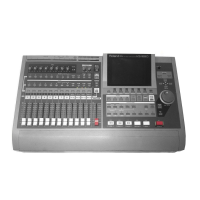
TEST MODE
Sep, 1998
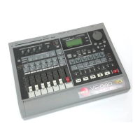
VS-880EX

 Loading...