rondo key-lock
®
INSTALLATION DETAILS
1 SPACINGS
Table 1 has been prepared for a batten spacing of
600mm. Confirm with your lining distributor that this
spacing is suitable for your lining board selection.
2 SELECTION
Choose the most appropriate Batten or Furring
Channel to suit your lining board.
3 DIRECT FIX AND INSTALL
Refer to Figures 1– 4 for the direct fix clip relevant for
your batten/furring channel choice.
4 SUSPENDED CEILINGS
If your ceiling needs to be suspended by more than
200mm, refer to the next page.
NOTE: For help with quantity take-offs, use the Rondo
Ceiling Design Wizard by downloading the Rondo App
or visiting our website.
TABLE 1: SPAN TABLE FOR INTERNAL USE
IN POPULATED RESIDENTIAL AREAS
600mm SPA CI NG S
BATTEN/FURRING
CHANNEL
PLASTERBOARD LINING
1 x 10mm 1 x 13mm
301/303 120 0 120 0
129 158 0 1540
308 1260 1240
547
to concrete
534 to
timber joist
534 to purlin
400mm max
272 Joiner against wall
for stability
200mm max
from wall
(For single layer
internal plasterboard ceilings)
100mm
100mm
121 Suspension Rod
Furring Channel
129/308
200mm max. span
if wall track is not used
Top Cross Rail 127
screw fix Furring Channel
to wall track
Locking key 139
Furring Channel
129/308
Top Cross
Rail127
TCR spacing
FC spacing
SUSPENDED CEILING INSTALLATION
For ceilings with more than 200mm suspension depth, a fully suspended system should be installed.
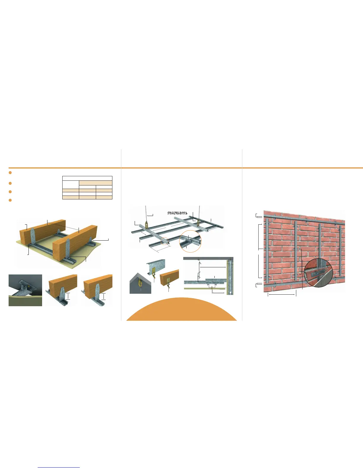
MASONRY WALL INSTALLATION
Rondo Furring Channels and adjustable clips are the ideal combination for battening out irregular walls,
ready for the fixing of building boards.
1. INSTALL CLIPS
Fix the adjustable BetaGrip
®
Clips to the masonry wall as figure 8 inset using either “knock-in” anchors or plugs
and screws. For timber framed wall use suitable screws. (See note on fixing alternatives for BetaGrip
®
Clips).
2. ATTACH FURRING CHANNEL
The BetaGrip
®
Clip has ‘notches’ to accept the furring channel, these are spaced approx 5mm apart.
Selecting the appropriate notch and using a rolling action clip the 129 or 308 Furring Channel into place.
Check the first Furring Channel for plumb and straightness and using this as a guide install the remaining
Furring Channels. For more minute adjustment of the clips for plumb etc., gently tap the prongs of the clip with
a hammer to adjust.
3. FIX PLASTERBOARD
Screw fix plasterboard, tape and set joints and sand off as lining manufacturers recommendations.
1. Fix Rondo 140 Wall Track (or 142 Wall Track if using the
308) around the perimeter of the ceiling
2. Secure hanger clips at a 1200mm x 1200mm grid pattern
ensuring the first Top Cross Rail is located within
200mm of abutting walls. If using multiple layers of
plasterboard consult the Rondo Professional Design
Manual.
3. Cut 121 Suspension Rod to required length and slide
into hanger clip tabs. Refer Figure 6.
4. Slide 2534 Clip onto the other end of the rod.
5. Secure 127 Top Cross Rail to the 2534 Clips with a
twisting action. Fit 139 Joiner Clips to Furring Channel
and then click into Top Cross Rail* firmly. Ensure 139
Clip engages in both sides: “click-clack”.
6. Secure Furring Channel to Top Cross Rail at a maximum
of 600mm apart or at appropriate spacings for your
lining choice, ensuring 5–10mm clearance is left
between end of Furring Channel and wall.
7. Framing can be leveled by adjusting the 2534 Clip by
squeezing tabs together.
8. See illustrations below for fixing and bracing details.
NOTE:
Distance between hangers supporting TCR = span of TCR
For more complex technical details, view the Rondo Professional Design
Manual or speak to a stockist in our Rondo Partner Network. Download a
copy of the Manual and locate a Rondo Partner by visiting our website.
For board fixing details, please see the plasterboard manufacturer.
FIGURE 5: KEY-LOCK
®
SUSPENDED CEILING
301 Batten with
314 Direct Fix Clip
129/308 Furring
Channel with
DIRECT FIX INSTALLATION
FIGURE 1: DIRECT FIX APPLICATIONS USING STANDARD RONDO COMPONENTS
FIGURE 2:
DIRECT FIX APPLICATION BENEATH CONCRETE
SLAB USING BG01 CLIP AND ONLY INSTALLED
WITH A CENTRE FIX
FIGURE 6: HANGER CLIPS
FIGURE 7: STABILISING THE SYSTEM
FIGURE 8: KEY-LOCK
®
USED TO BATTEN-OUT MASONRY WALL
FIGURE 3:
SUSPENDED APPLICATION USING 129/308
FURRING CHANNEL WITH 394 DIRECT FIX CLIP
FIGURE 4:
DIRECT FIX CLIP 305 IN SUSPENDED
APPLICATION TO A RECOMMENDED
MAXIMUM OF 100mm FOR 301 BATTEN
Maximum spacings:
For 308: 900mm
For 129: 1200mm
25mm
25mm
600mm maximum
Anchor clips
(eg. BETAGRIP)
BetaGrip
®
Clips can be
installed to a wall with
either one centre fixing
or two, as shown, for better
security on rough surfaces
 Loading...