EasyManuals Logo

Rosemount 8800D Series User Manual

Rosemount 8800D Series
172 pages
To Next Page IconTo Next Page
To Previous Page IconTo Previous Page
Page #33 background imageLoading...
Page #33 background image
Reference Manual
00809-0100-4004, Rev BA
August 2010
2-23
Rosemount 8800D
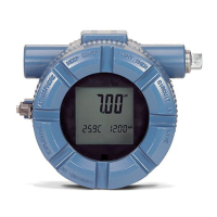
The indicator features an eight-character (and five alphanumeric) liquid
crystal display that gives a direct reading of the digital signal from the
microprocessor. During normal operation, the display can be configured to
alternate between the following readings:
1. Primary variable in engineering units
2. Percent of range
3. Totalized flow
4. 4–20 mA electrical current output
5. Shedding Frequency
6. Electronics Temperature
7. Pulse Output Frequency
8. Process Temperature
(MTA Option Only)
9. Mass Flow
10. Volume Flow
11. Velocity Flow
12. Calculated Process Density
(MTA Option Only)
Figure 2-18 shows the indicator display with all segments lit.
A HART-based communicator can be used to change the engineering units of
the parameters displayed on the indicator. (See Section 4: Operation for more
information).
Figure 2-18. Optional Liquid Crystal Display

Table of Contents

Questions and Answers:

Question and Answer IconNeed help?

Do you have a question about the Rosemount 8800D Series and is the answer not in the manual?

Rosemount 8800D Series Specifications

General IconGeneral
TypeVortex Flow Meter
Measurement PrincipleVortex Shedding
Operating Temperature-40 to 185°F (-40 to 85°C)
Storage Temperature-40 to 185°F (-40 to 85°C)
Communication ProtocolsFOUNDATION Fieldbus
Material316 stainless steel
Fluid TypeLiquid, Gas, Steam
Line Size1/2 to 8 inches (15 to 200 mm)
ApprovalsATEX, IECEx, CSA, FM
Output Signal4-20 mA
Process ConnectionFlanged, Wafer, Threaded
Electrical ConnectionM20
Protection RatingIP66
Mounting StyleWafer, Flanged

Related product manuals