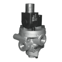
Construction: Poppet.
Mounting Type: Inline.
Flow Media: Filtered air.
Pilot Pressure: Must be equal to or greater than inlet pressure.
For vacuum service models requiring external pilot supply, a
pilot pressure of at least 30 psig (2.1 bar) is required.
Safety Integrity Level (SIL) – Certified by TÜV Rheinland in
accordance to IEC 61508 and IEC 61511 safety integrity level
2 (SIL 2) and EN ISO 13849-1, PL c or PL d (with application
specific diagnosis) in singular application with HFT = 0 and SIL
3 and PL e in redundant application with HFT ≥1.
Pressure Controlled
Ambient/Media Temperatures:
High Temperature: 0° to 300°F (-17° to 150°C).
Low Temperature: -40° to 175°F (-40° to 80°C).
For temperatures below 40°F (4°C) air must be free of
water vapor to prevent formation of ice.
Inlet Pressure: 30 to 150 psig (2 to 10 bar).
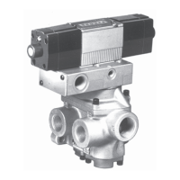
Solenoid Pilot Controlled
Solenoids: Rated for continuous duty. Voltage and
hertz ratings shown on pilot housing.
Power Consumption:
Single Solenoid: 87 VA inrush, 30 VA holding on AC;
14 watts on DC.
Double Solenoid: Each solenoid, 190 VA inrush,
40 VA holding on AC; 20 watts on DC.
Ambient Temperature:
High Temperature: 0° to 250°F (-17° to 122°C).
Low Temperature: -40° to 120°F (-40° to 50°C).
Media Temperature:
High Temperature: 0° to 300°F (-17° to 150°C).
Low Temperature: -40° to 175°F (-40° to 80°C).
Inlet Pressure:
Port Sizes 1/4 to
1½
: 15 to 150 psig (1.0 to 10 bar).
Port Sizes
1½
to
2½
: 30 to 150 psig (2 to 10 bar).
Pneumatic equipment should be maintained only by persons
trained and experienced in the maintenance of such equipment.
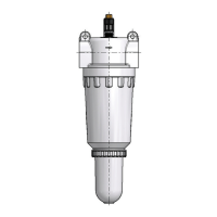
Supply Clean Air. Foreign material lodging in valves is a major cause
of breakdowns. The use of an air filter located close to the valve is
strongly recommended. The filter bowl should be drained regularly, and
if its location makes draining difficult, the filter should be equipped with
an automatic drain.
Check Lubricator Supply Rate. A lubricator should put a fine oil mist
into the air line in direct proportion to the rate of air flow. Excessive
lubrication can cause puddling in the valve and lead to malfunctions.
For most applications an oil flow rate in the lubricator of one drop per
minute is adequate (note that this valve itself does not require air line
lubrication, but some optional adaptors do, i.e., air index, etc.).
Compatible Lubricants. Although this valve does not require air line
lubrication, it may be used with lubricated air being supplied to other
mechanisms. Some oils contain additives that can harm seals or other
valve components and so cause the valve to malfunction. Avoid oils with
phosphate additives (e.g., zinc dithiophosphate), and diester oils; both
types can harm valve components. The best oils to use are generally
petroleum base oils with oxidation inhibitors, an aniline point between
180°F (82°C) and 220°F (104°C), and an ISO 32 or lighter viscosity.
Some compatible oils are listed above at the right. These oils, although
believed to be compatible, could change without notice because
manufacturers sometimes reformulate their oils. Therefore, use oils
specifically compounded for air line service. If it is a synthetic oil, contact
the oil manufacturer for compatibility information.
Cleaning the Valve. If the air supplied to the valve has not been well
filtered, the interior of the valve may accumulate dirt and varnish which
can affect the valve’s performance. A schedule should be established
for cleaning all valves, the frequency depending on the cleanliness of
the air being supplied.
IMPORTANT NOTE: Please read carefully and thoroughly
all the CAUTIONS and WARNINGS on page 4.
COMPATIBLE LUBRICANTS
Maker Brand Name
Amoco ......................American Industrial Oil 32
Amoco Spindle Oil C, Amolite 32
Citgo ........................ Pacemaker 32
Exxon .......................Spinesstic 22, Teresstic 32
Mobil .........................Velocite 10
Non-Fluid Oil ............Air Lube 10H/NR
Shell .........................Turbo T32
Sun ........................... Sunvis 11, Sunvis 722
Texaco ......................Regal R&O 32
Union ........................ Union Turbine Oil
2
ROSS CONTROLS
®
VALVE SPECIFICATIONS
VALVE MAINTENANCE
To clean the valve use any good commercial solvent.
Do not scrape varnished surfaces. Also do not use
chlorinated solvents or abrasive materials. The former
damages seals, and abrasives can do permanent
damage to metal parts. Before reassembling the valve,
lubricate all sliding surfaces with a grease such as
MobilGrease 28.
Electrical Contacts. In the electrical circuits associated
with the valve solenoids, keep all switches or relay
contacts in good condition to avoid solenoid malfunctions.
Replace Worn Components. In some cases it is not
necessary to remove the valve from its installation for
servicing. However, turn off the electrical power to the
valve, shut off the air supply, and exhaust the air in the
system before beginning any disassembly operation.
Service kits for these valves are listed on page 3.
 Loading...