10
Operating instructions G series UTD.187.2019.09.00_EN
UTD.187.2019.09.00_EN Operating instructions G series
Nut seating
Bolt or nut seating
(maximum length stated in the table)
Bolt or nut seating
(maximum length stated in the table)
•
•
•
•
•
•
•
•
•
•
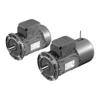
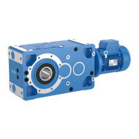
5.4 - Foot mounting
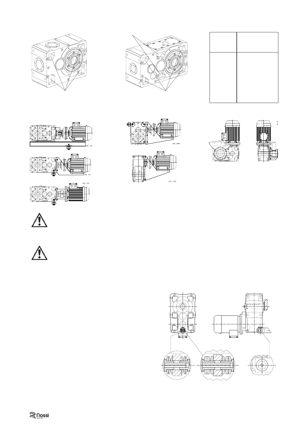
5.5 - Shaft mounting
Important! When shaft mounted, the gear reducer must be supported both axially and radially (also
for mounting position B3 ... B8) by the machine shaft end, as well as anchored against rotation only,
by means of a reaction having freedom of axial movement and suffi cient clearance in its couplings
to permit minor oscillations always in evidence without provoking dangerous overloading on the gear
reducer. Lubricate with proper products the hinges and the parts subject to sliding; when mounting the
screws it is recommended to apply locking adhesives.
Important! Concerning the reaction system, follow the project indications stated in the technical
catalogs Rossi. Whenever personal injury or property damage, due to falling or projecting parts of gear
reducer or of its parts, may occur, foresee adequate supplementary protection devices against:
– rotation or unthreading of the gear reducer from shaft end of driven machine following to
accidental breakage of the reaction arrangement;
– accidental breakage of shaft end of driven machine.
System kit using reaction disc springs (reaction recess).
For the mounting of the kit, use the tapped butt end
hole on the shaft end of the driven machine and the
fl at machined chamfered surface for compressine and
fi tting the disc springs into the reaction recess.
(50 ... 81, 125) (100)
Fig. 5.4.1. Bolts for foot fastening
UT.C 2119
Gear red.
size
Screw
UNI 5737-88
(l max)
40
M6 × 22
50
M8 × 30
63, 64
M10 × 35
80, 81
M12 × 40
100
M14 × 50
125, 140
M16 × 55
160, 180
M20 × 70
200, 225
M24 × 90
250, 280
M30 × 110
320 ... 360
M36 × 130
 Loading...