9
UTD.187.2019.09.00_EN Operating instructions G series
Tab. 5.2.1. Tightening torque Ms for feet and fl ange fastening bolts
Screw Ms [N m]
NI 5737-88, UNI 5931-84
cl. 8.8 cl. 10.9 cl. 12.9
M4 2.9 4 –
M5 6 8.5 10
M6 11 15 20
M8 25 35 40
M10 50 70 85
M12 85 120 145
M14 135 190 230
M16 205 290 350
M18 280 400 480
M20 400 560 680
M22 550 770 930
M24 710 1000 1200
M27 1000 1400 1700
M30 1380 1950 2350
M33 2000 2800 3400
M36 2500 3550 4200
5.2 - Tightening torques for fastening bolts (foot, fl ange, accessories) and for plugs
Unless otherwise stated, usually it is suffi cient to use screws in class 8.8;
- Before tightening the bolt be sure that the eventual centering of fl anges are inserted properly
- The bolts are to be diagonally tightened with the maximum tightening torque (see table 5.2.1).
Before tightening, carefully degrease the screws; in the event of heavy vibrations, heavy duties, frequent drive
inversions apply a thread-braking seal type Loctite or similar.
1) With B5 flange type B: 14 n.4 (M12).
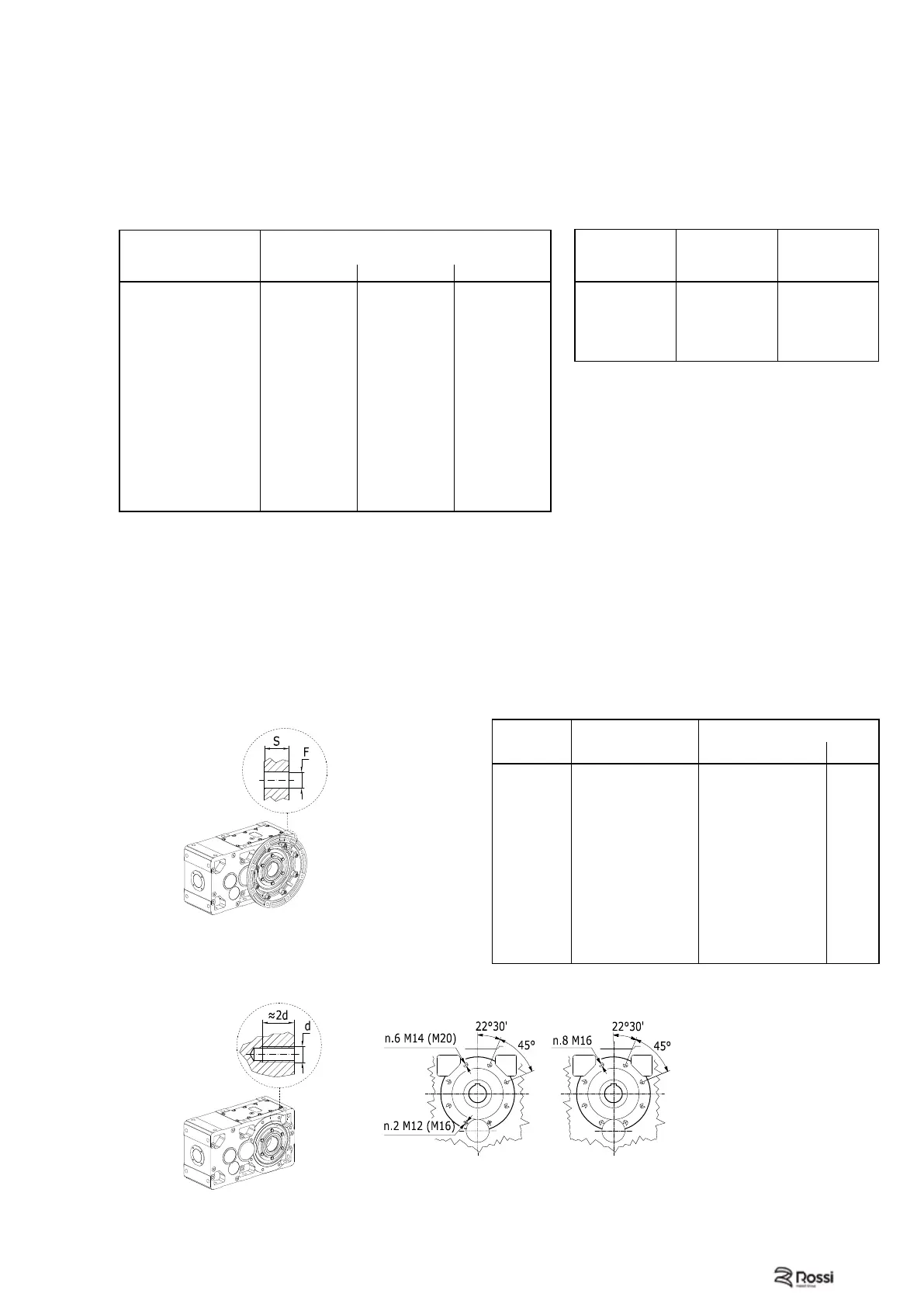
Fig. 5.3.2. B14 Flange
5.3 - Flange mounting
Carefully select the length of fi xing screws when using tapped holes (B14 fl ange) for gear reducer fi tting, in
order to assure a suffi cient meshing thread length for the correct gear reducer fi tting to the machine without
breaking down the threading seat.
For the mounting of sizes 140, 200 and 250 including B14 fl ange it is necessary that the tapped holes of
counterfl ange (driven machine) are realized with the same diameter (equal to Ø15, Ø21 and Ø25 respectively)
ase the 2 tapped holes of lower diameter are not exactly in position 22° 30'.
In the fastening screws and in the fl ange mating surfaces use locking adhesives.
Sizes 140, 200 Size 250
Gear red. size
Dimension
of threading
Ms
[N m]
40, 50
G 1/4’’ 7
63 ... 81
M16 × 1,5 14
100 ... 140
G 1/2’’ 14
160 ... 280
G 3/4’’ 14
320 ... 360
G 1’’ 25
Tab. 5.2.2. Tightening torques for plugs
Tab. 5.3.1. Dimension and fl ange hole numbers B5 and B14
B5 Flange
B5 Flange (type B)
Fig. 5.3.1.
Fig. 5.3.3. Drilling B14 for sizes 140, 200 and 250.
Gear red. size Flange B14
d
Flange B5
ØF S
40 M5 n. 4 9,5 n. 4 (M8) 11
50 M6 n. 4 9,5 n. 4 (M8) 12
63, 64 M8 n. 4 11,5
1)
n. 4
1)
(M10
1)
) 14
80,81 M10 n. 4 14 n. 4 (M12) 16
100 M12 n. 4 14 n. 4 (M12) 18
125 M14 n. 7 18 n. 4 (M16) 20
140 M14 n. 6 + M12 n. 2 18 n. 4 (M16) 22
160, 180 M16 n. 8 18 n. 8 (M16) 22
200 M20 n. 6 + M16 n. 2 18 n. 8 (M16) 25
225 M20 n. 8 22 n. 8 (M20) 25
250 M24 n. 6 + M20 n. 2 27 n. 8 (M24) 30
280 M24 n. 8 27 n. 8 (M24) 30
320 ... 360 M30 n. 8 33 n. 8 (M30) 37
 Loading...