The circuit breaker must be closed to the PS-x25 and must be
accessible.
3.1 Mounting
The PCB mounting holes dimensions for the C-box are provided in
Figure 3.
Figure 3: PCB Mounting Holes Dimensions
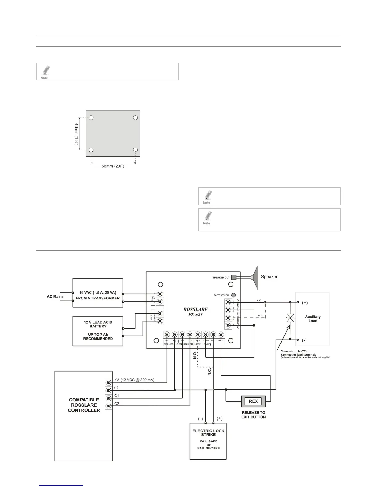
3.2 Wiring
Refer to the wiring diagram in Section 4.
1. Mount the PS-x25 within the secured perimeter.
2. Connect AC power (16.5 VAC, 60 Hz to the marked terminals, "~
VIN ~". Use a Class 2 transformer such as DSC Part No.
PTC1640U.
Use 18 AWG or larger for all power connections (battery, DC
output).
Ensure that the power-limited circuit is wired separately from the
non-power limited wiring (16.5 VAC, battery)
3. Connect the ACU’s power input to the power terminal marked
[SECURED CONTROLLER +V and (-)]
4. Connect the two lock outputs to the power terminal marked
[LOCK 12VDC N.C or N.O]
5. Connect the auxiliary relay if needed.
6. [OPTIONAL] Connect the battery terminal to power terminal
marked [12V DC +Bat and (-)] (Battery leads included)
A backup battery is optional. When a battery is not used, loss of
AC results in the loss of output voltage. When using a backup
battery, it must be a UL certified "lead acid" or "gel" type.
7. Panic hardware shall not be used with this device.
3.3 Maintenance
For proper operation, the unit should be tested at least once a year.
3.3.1 Output Voltage Test
Check DC output for proper voltage level under normal load
conditions.
3.3.2 Battery Test
Check specified voltage, at both battery terminal and board terminals
marked [12VDC +Bat and (-)] under normal load conditions, verify that
the battery is fully charged and insure there is no break in the battery
connection wires.
 Loading...