6
Fig. 8
9. Anchoring The Ramps And Spotting Dish:
A. Ramps:
Note the ramps use a 1/2” diameter anchor which is different
from the lift. Using a 1/2" carbide drill bit, drill holes and install
(4) anchors to the ramps.
B. Wheel Dish:
1. Locate front wheel dish as shown in Fig. 7 (C).
2. Drill two 3/8" holes x 2-1/2" deep in concrete floor using holes in
wheel spotting dish as guide.
3. Hammer both drive anchors through wheel spotting dish into
concrete floor.
10. Installing Hose Guard:
Note: Hose guards ARE NOT to be used if conduit is in concrete.
A. Postion hose guard over hose. Note: Hose guard is to be used
to prevent damage of hose when driven over and to prevent
tripping.
B. Drill (4) 1/4" anchor holes and install anchors.
RAMP CLEARANCE TABLE
A 1/2" (13mm) minimum clearance.
B 5/8" (16mm) minimum clearance.
C Anchor hole locations for wheel dish.
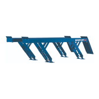
7. Positioning The Ramps:
A. The ramps should be positioned as shown in Fig. 7, with a
minimum of 1/2” (3mm), Dimension (A), clearance between the
ramp and the front edge of the pad opposite the cylinders and
5/8” (16mm), Dimension (B), clearance between the outside
surfaces of the pad and the inside surface of the ramps. DO
NOT DRILL ANCHOR HOLES AT THIS TIME!
B. Raise and lower the lift through one cycle and ensure there is
adequate clearance between the ramps and the pad.
8. Installing The Lock Release Handle:
A. Insert the latch release handle through the access hole in the
ramp nearest the power unit.
B. Insert the keyed end of the handle through the keyway in the
latch release weldment as shown in Fig. 8.
C. Install the roll pin into the end of the handle as shown in Fig. 8.
Fig. 7
B
B
A
A
C
C
7"
(178mm)
9-1/2"
(241mm)
9-1/2"
(241mm)
16"
(406mm)
B
B
A
A
C
C
7"
(178mm)
9-1/2"
(241mm)
9-1/2"
(241mm)
16"
(406mm)
VLXS10 VLXS7
 Loading...