Reference
Modification no.
- 0 -
Page
232
Date
1997 02 01
Main
914 F
01480
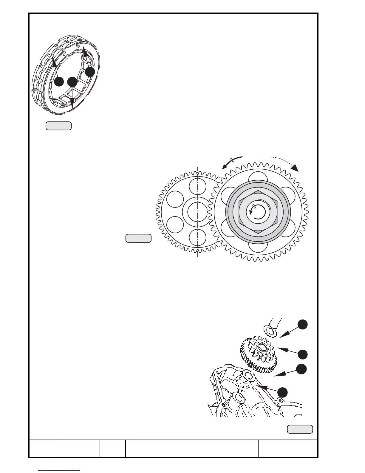
14.2.3) Sprag clutch — installation
See Pic. 202, 204, 205 and 206.
Place sprag clutch into clutch housing with brake clip E visible. At fitting
of brake clip, compress slightly using circlip pliers and ensure that clip
remains in position and engages fully on the catches in sprag unit {. Fit
retaining ring W.
Lock crankshaft using fixing screw 241 965. Degrease taper and threads
of crankshaft and taper of clutch housing. Coat taper of clutch housing
thinly with LOCTITE 221 and fit on crankshaft. Turn free-wheel gear to
facilitate aligning of the sprags E.
◆ NOTE: The free-wheel gear } gear must engage on crankshaft
when turning anti-clockwise, looking towards magneto side
of engine, and turn freely when turning clockwise.
Secure degreased hex. nut M34x1,5
with LOCTITE 221 and tighten to
120 Nm (1060 in.lb).
◆ NOTE: Hex. nut with left hand thread.
■ ATTENTION: Check axial clearance of free-wheel gear, see Pic. 202 and
dimension P in Chapter 15).
14.2.4) Reduction gear for electric starter
See Pic. 207.
Place thrust washer Q 12,5/21,5/1 onto crankcase. Place
intermediate gear W into position, lubricate intermediate
gear shaft E and push into position. Fit thrust washer
R 12,5/21,5/1 on top of it.
14.2.5) Fitting of ignition housing
See Chapter 13.3.9).
5
11
3
Pic. 206
4
3
2
1

 Loading...


