7 Installation
Installer reference guide
34
RVLQ05+08CAV4 + RHYHBH05AA + RHYHBH/X08AA +
RHYKOMB33AA
ROTEX HPU hybrid
4P355635-1 – 2013.05
Routing Possible cables (depending on unit type and installed options)
a ▪ Interconnection cable between indoor and outdoor unit
▪ Normal kWh rate power supply
▪ Preferential kWh rate power supply
▪ Heat pump convector (option)
▪ Room thermostat (option)
▪ 3-way valve (option in case of tank)
▪ Shut-off valve (field supply)
▪ Domestic hot water pump (field supply)
b ▪ Interconnection cable between indoor unit and gas boiler (see boiler manual for connection instructions)
c ▪ Outdoor ambient temperature sensor (option)
▪ User interface
▪ Indoor ambient temperature sensor (option)
▪ Electrical meter (field supply)
▪ Preferential power supply contact
▪ Gas meter (field supply)
3 Fix the cable with cable ties to the cable tie mountings to
ensure strain relief and to make sure that it does NOT come in
contact with the piping and sharp edges.
CAUTION
Do NOT push or place redundant cable length in the unit.
NOTICE
More technical specifications of the different connections
are indicated on the inside of the indoor unit.
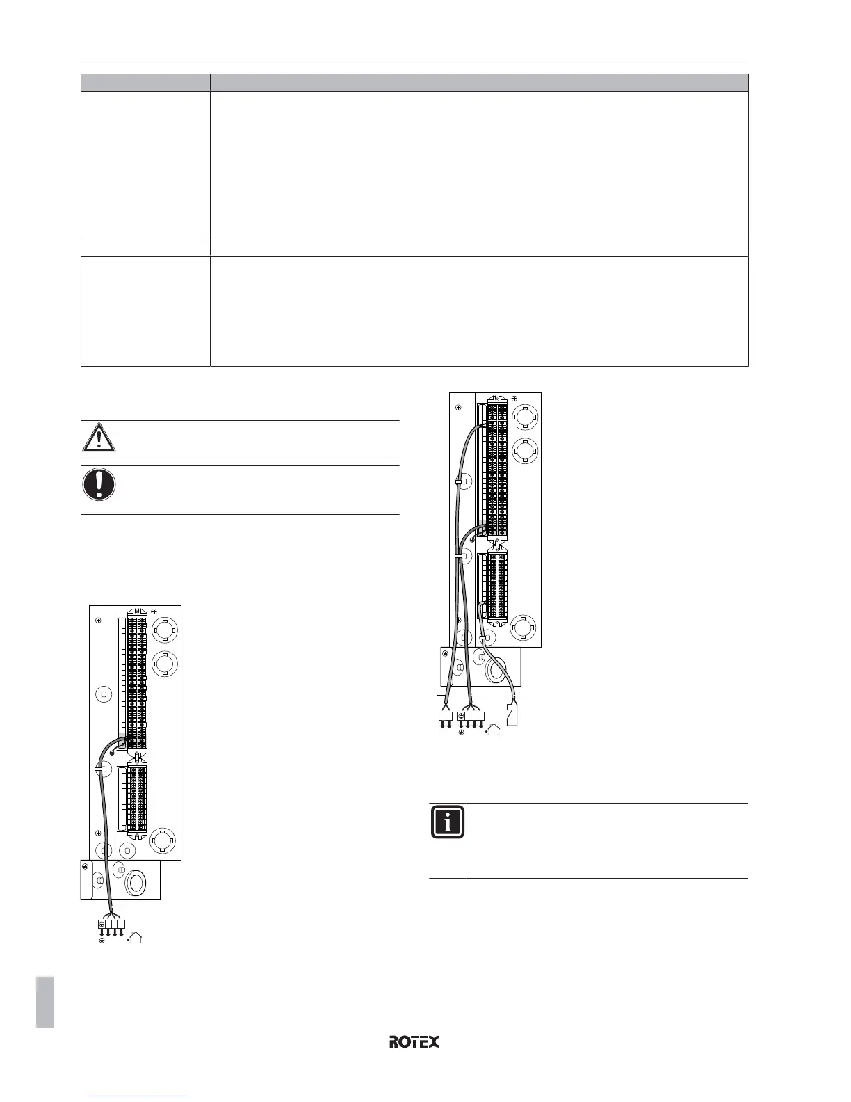
7.8.4 To connect the main power supply of the
indoor unit
1 Connect the main power supply.
In case of normal kWh rate power supply
X2M
X1M
1
2
3
X5M
123
123
a
Legend: see illustration below.
In case of preferential kWh rate power supply
30
31
S1S
X2M
X1M
1
3
4
2
3
X5M
LN
LN
c
123
123
b
a
a
Interconnection cable (=main power supply)
b
Normal kWh rate power supply
c
Preferential power supply contact
2 Fix the cable with cable ties to the cable tie mountings.
INFORMATION
If the system is connected to a preferential kWh rate power
supply, a separate normal kWh rate power supply is
required. Change connector X6Y according to the wiring
diagram on the inside of the indoor unit.

 Loading...


