15Section 7 — Service
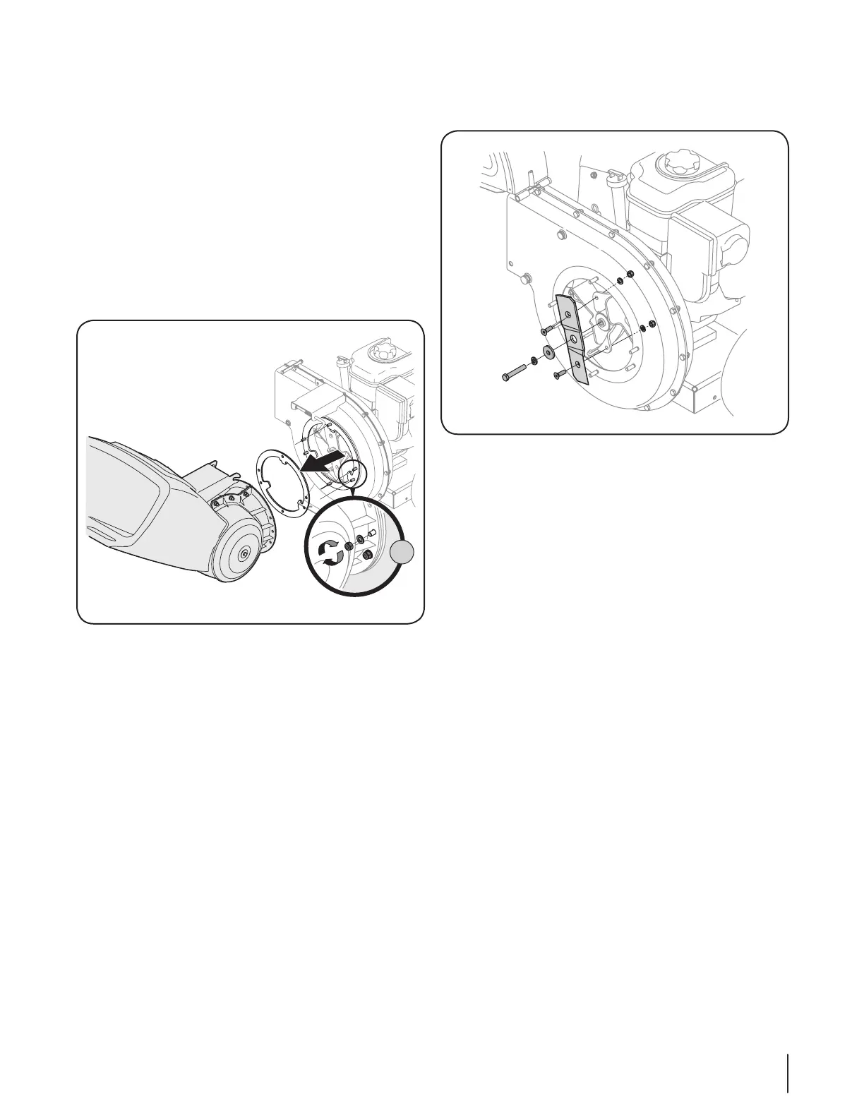
8. Remove the two internal hex screws (a), lock washers (b),
and hex lock nuts (c) which secure the shredder blade to
the impeller. See Figure 7-4.
(f)
(e)
(d)
(a)
(a)
(b)
(b)
(c)
(c)
Figure 7-4
9. Remove the hex bolt (d), lock washer (e), and flat washer (f)
to completely free shredder blade. See Figure 7-4.
IMPORTANT: When reassembling the shredder blade,
tighten center bolt to between 550 and 700 in.-lbs. and the
two outside bolts to between 250 and 350 in.-lbs.
NOTE: Use a 3/16” hex key (Allen) wrench on the outside
of the shredder blade and a 1/2” box (or socket) wrench
on the inside of the shredder blade. Hold the Allen wrench
stationary and rotate the box (or socket) wrench to loosen
the nut. Use caution when removing the blade to avoid
contacting the weld studs on housing.
IMPORTANT: When sharpening the blade, follow the
original angle of grind as a guide. It is extremely important
that each cutting edge receives an equal amount of
grinding to prevent an unbalanced blade. An unbalanced
blade will cause excessive vibration when rotating at high
speeds and may cause damage to the unit. The blade can
be tested by balancing it on a screwdriver or nail. Remove
metal from the heavy side until it is balanced evenly.
Off-Season Storage
• When storing the chipper shredder in an unventilated or
metal storage shed, care should be taken to rustproof the
non-painted surfaces. Using a light oil or silicone, coat the
equipment, especially any springs, bearings, and cables.
• Remove all dirt from exterior of engine and equipment.
• Follow lubrication recommendations.
• Refer to engine manual for correct engine storage
instructions.
• Store equipment in a clean, dry area. Do not store in an
area where equipment is present that may use a pilot light
or has a component that can create a spark.
Shredder Blade
1. Stop the engine and make certain that all moving parts
have come to a complete stop.
2. Disconnect the spark plug wire and ground against the
engine.
3. Lower the hopper assembly and block up the housing.
4. Remove the six hex lock nuts (a) and flat washers (b) from
the weld studs on the flail housing. See Figure 7-3 inset A.
Retain the hardware.
5. Carefully separate the hopper assembly from the impeller
assembly and remove the support plate. See Figure 7-3.
NOTE: When reassembling the support plate, make certain
the embossed tab faces inward towards the impeller.
A
Model Series 460 Shown
(a)
(b)
Figure 7-3
6. Remove the two wing knobs and cupped washers that
secure the chute deflector and raise the chute.
7. Insert a 1/2” or 3/4” diameter pipe through the flail screen
into the impeller to keep it from turning or remove the flail
screen and insert a piece of wood into the chute opening.
 Loading...