ENGINE K SERIES 1.8 VVC
Technical Academy
01-34-RG-W-Ver:1 Page 13 of 28
Cylinder Head (Dismantle)
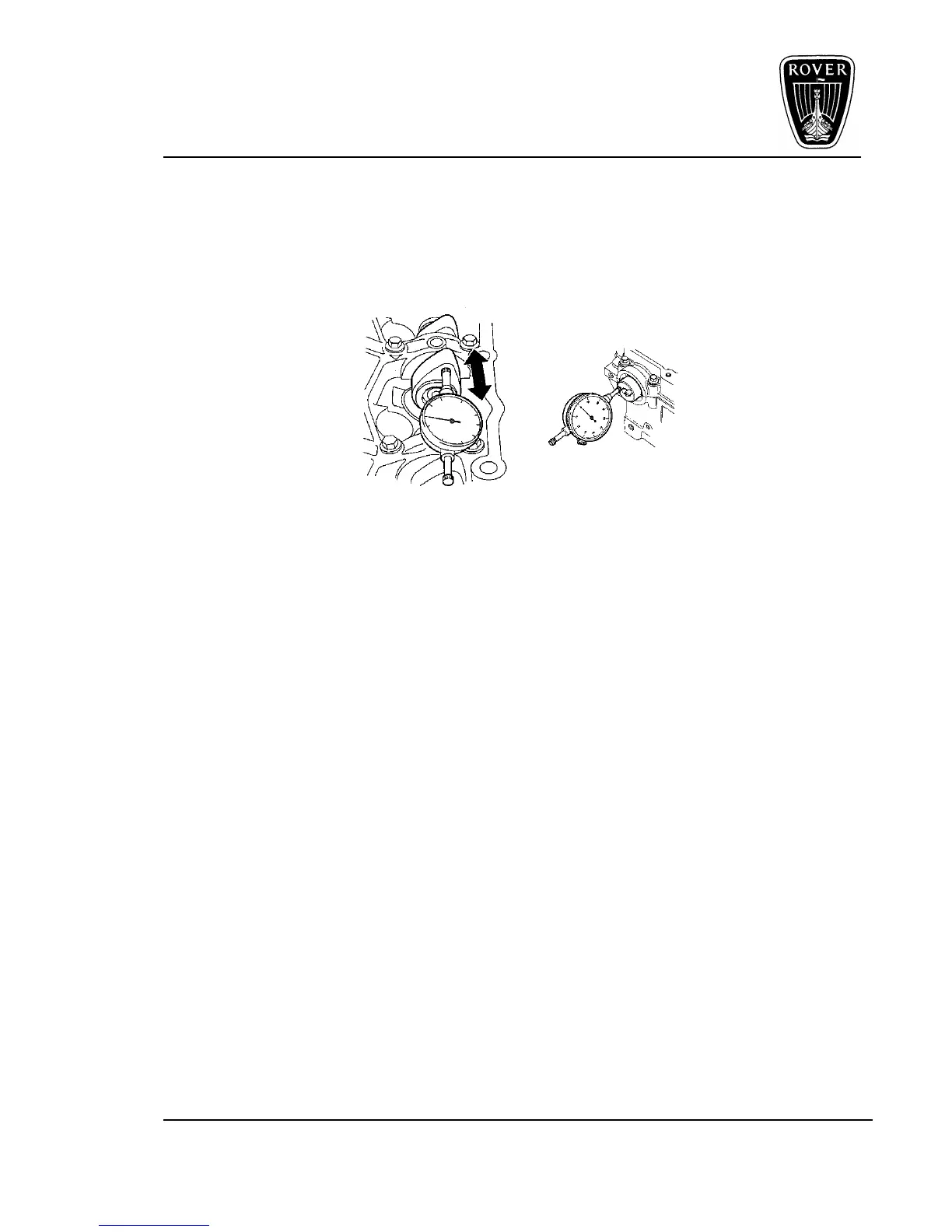
Camshaft End-float
Before removing the camshaft carrier, check the camshaft end-float.
This is done by fitting a suitable DTI to the camshaft carrier with the stylus contacting the
face of number 4 front inlet camshaft lobe as shown.
Figure 12
• Push the camshaft fully rearward and zero gauge, then move camshaft fully forward
and note gauge reading.
• Repeat the same procedure for the rear inlet camshaft with stylus contacting the face
of number 5 lobe.
• Check the end-float on the exhaust camshaft adopting the same procedure, positioning
the DTI on the front end of the camshaft.
Renew components as necessary to achieve the correct end-float.
Inlet Camshaft End-float:
0.03 to 0.15 mm
Service Limit = 0.25 mm.
Exhaust Camshaft End-float:
0.06 to 0.19mm
Service Limit = 0.3 mm.
 Loading...