Do you have a question about the RTA X-PLUS ET B4 Series and is the answer not in the manual?
Defines terms used in the manual, referencing figure 1 for clarity.
Explains the manual's purpose and recommends reading it fully before operation.
Discusses the wide application range and encourages contacting RTA for specific needs.
Defines "user and customer" as a skilled person, referencing chapter 2.7.
States the manual is valid at the time of sale and RTA reserves revision rights.
States drives are suitable for 4, 6, or 8-terminal stepping motors, not 5-terminal.
Covers installation environment, pollution, flammable materials, and usage restrictions.
Addresses professional installation, electrical limits, protection, and earth grounding.
Details safe operation, avoiding powered-on work, repair, and thermal hazards.
Covers liability limitations and references to STO/Monitor output usage in Chapter 12.
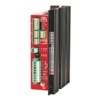
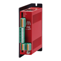
Provides physical dimensions of X-PLUS ET B4 and S4 drives with diagrams.
Explains the model identification scheme for X-PLUS ET X4.Y series drives.
Details C3a inputs, their voltage limits, and terminal numbers for auxiliary inputs.
Lists C5 terminals for 24 VDC logic supply input.
Details STO1 and STO2 input terminals and shield connection for STO cables.
Describes C2 auxiliary outputs (02, 01, 00) and their functions, including BRAKE and EDM.
Details C4 connector terminals for encoder inputs and power supply, including cable colors.
Explains the RJ-45 connectors for EtherCAT communication and their pinout.
Lists C1 terminals for motor windings and power supply, and C5 for logic supply.
Emphasizes earth terminal connection and proper grounding points for safety.
States the drive is Protection Class I, requiring attention to earth connections for protection.
Presents tables detailing AC input and motor phase output electrical characteristics.
Defines terms like HVnomAC, LVnomDC, Max input current, Max input power, VPH, and INP.
Discusses setting drives for different motors/applications and the role of LEDs.
Shows the position of EtherCAT connectors on the drive's high side.
Explains the meaning of LED indicators (HV, FAU, TER) for EtherCAT communication status.
Cautions on dimensioning power for filters, protection systems, and transformers based on drive/motor needs.
Warns about required protection systems like SPD, residual current devices, and fuses.
Warns to use copper wire rated for 60/75°C and to select conductor cross-section correctly.
States IP20 protection and user responsibility for providing a suitable enclosure.
Details installation environment conditions: class 3K3, pollution degree 2, and mechanical class 3M1.
Specifies storage temperature, humidity, and environment class (1K3).
Advises on heat dissipation, drive orientation, and maintaining free space around the drive.
Lists routine maintenance checks: connector tightness, logic signals, earth connections, and cleaning.
States that faulty drives must be returned to RTA for repair; no self-repair.
Notes that examples are for general logic I/O and not for STO/MONITOR functions.
Shows interfacing a logic output with a PNP input control system.
Demonstrates driving a micro-relay using a logic output.
Shows interfacing a logic input with a NPN open collector output control system.
Demonstrates interfacing a logic input with a PNP output control system.
Shows connection example with a TOTEM-POLE (PUSH-PULL) output control system.
Covers EMC, interference reduction, logic immunity, compliance, and grounding conflicts.
Lists suggested limits for nominal motor current and phase inductance for X-PLUS ET drives.
Discusses reverse energy, equalization, motor losses, and heating.
Describes the system configuration for STO functions, including safety unit and emergency stop.
Defines the Safe Torque Off (STO) function and its purpose in reducing injury risks.
Explains how STO function disables motor winding current via independent channels.
Lists safety standards (IEC 61800-5-2, IEC 61508 SIL3) met by the STO function.
Warns to assess risks associated with the overall equipment before activating safety functions.
Highlights residual risks even with STO active, like motor coasting and gravity effects.
Details STO input connections (C3b) and output monitoring connections (C2).