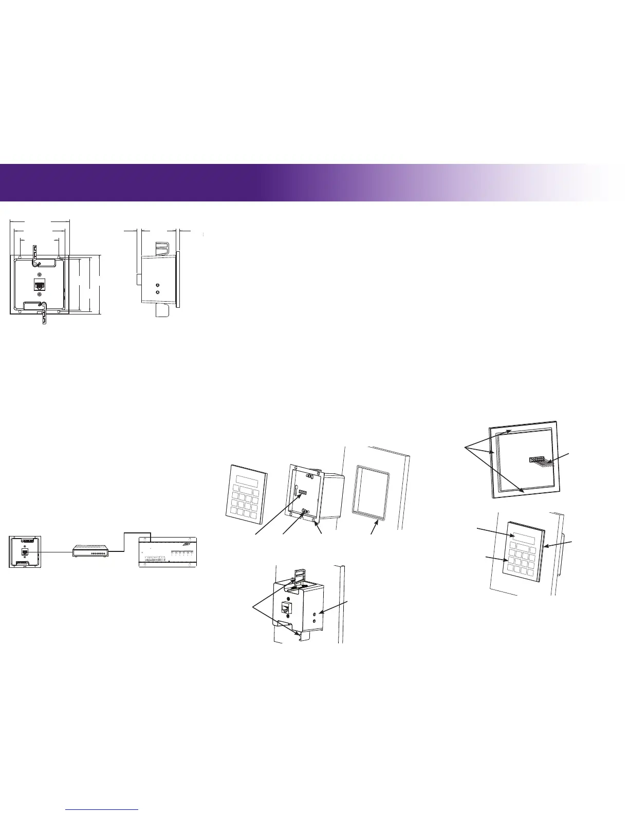
Cutout (WxH): 2.967” (75.4mm) x 3.145”(79.9mm)
Outside edge (WxH): 3.425”(87mm) x 3.425”(87mm)
Depth in-wall (including Ethernet jack): 2.36”(59.95mm)
MOUNTING HEIGHT
The recommended mounting height for the WK2 is between 54 inches (1.37m)
and 60 inches (1.52m) from the bottom of the glass keypad.
REAR HOUSING INSTALLATION
Two mounting wings (included) may be used to secure the WK2 to drywall.
Alternate methods of mounting the rear housing include:
• A metal conduit box (sold separately) is available for new construction and
installations that require a metal enclosure.
• Four screw holes located on the rear housing may also be used for mounting
in situations where mounting wings are not possible (wood paneling, concrete
etc). Visit the WK2 product support webpage for more information.
IMPORTANT NOTES:
• Testing the WK2 power up and Ethernet activity MUST be done prior to
applying the adhesive used to secure the unit during installation (see steps
below). Once the adhesive is used, it will be very difcult to remove the WK2.
INSTALLATION USING MOUNTING WINGS:
1. Use the included cut-out template to mark and cut the opening in the wall.
2. Test WK2 power up and activity. Pull Ethernet cable though wall opening
and plug it in to test the WK2 power up and activity. Activity LED lights are
viewable through two rear housing holes (see diagram below).
3. Remove the glass keypad from the rear housing assembly by pulling apart
gently - DO NOT twist or tilt the glass keypad side to side during removal.
4. Install the mounting wings on to the rear housing. Place a mounting wing on
the rear housing in the appropriate orientation (see diagram), aligned with
the screw hole, insert the screw and tighten until the screw protrudes from
mounting wing slightly. Repeat for mounting wing on opposite side.
5. For waterproof installations (optional): Test t rear housing assembly in
wall opening and remove. Seal along the edge of the wall opening with a bead
of silicone or paintable latex sealant. (* See diagram below)
6. Place rear housing assembly (glass keypad removed) in the wall opening and
align, then tighten the mounting wing screws until snug - DO NOT over-
tighten.
It’s Under Control
®
COMMUNICATION AND CONTROL
The WK2 is powered using Power-Over-Ethernet (PoE).
IMPORTANT NOTES:
• An 802.3af compliant Power-over-Ethernet router/switch (Class #2) must be
used to avoid potential performance issues or damage to the unit.
• The WK2 CANNOT be powered from an external power supply, an RTI CB8
connecting block or an RTI control processor.
POWERING THE WK2
WK2
MOUNTING
WK2 (Rear)
RESET
ETHERNET
EXPANSION
PORT 1 PORT 2 PORT 3
PORT 4
PORT 5
PORT 6
+
+ +
+ +
+
USB
RTI COM
POWER
STATUS
RS-232
POWER / IR
+12VDC TRIGGER
+3-24VDC SENSE
RELAYS (+30VDC, 5A MAX)
IR OUTPUT LEVEL
1
2
Model XP-6
Advanced Control Processor
RTI XP-6
Silkscreen Graphics
May 27, 2010
Scale 1:1
DOCUMENT NO.
REV
ECO
REVISION RECORD
DESCRIPTION
DRFT
A
B
C
D
1234
D
C
B
A
4 3 2 1
DATE
MM(INCH)
25.4MM=1 INCH
TOLERANCES EXCEPT AS NOTED
MM
0
±
.0
±
.00
±
ANGLES
±
MATERIAL
FINISH
INCHES
.0
±
.00
±
.000
±
DATE
DATE
DATE
DATE
DFTG
CHKD
MFG
APPVL
INTERPRET PER ANSI Y14.5
THIRD ANGLE PROJECTION
MODEL
TITLE
SIZE
DO NOT SCALE DRAWING
DET LISTS
YES
NO
SHT OF
REV
REMOTE TECHNOLOGIES INC.
SHAKOPEE, MN 55379
DOCUMENT NO.PART NO.
THIS IS AN UNPUBLISHED WORK CONTAINING REMOTE
TECHNOLOGIES INC. CONFIDENTIAL AND PROPRIETARY
INFORMATION. DISCLOSURE, USE OR REPRODUCTION
WITHOUT THE WRITTEN AUTHORIZATION OF REMOTE
TECHNOLOGIES INC. IS STRICTLY PROHIBITED.
01 ----- ----- PRELIMINARY RELEASE DRF
WK-2 USER MANUAL
01
1 1
ASSEM . WK-2-TOTAL
RTI 01/15/15
°
0.850SCALE
(Cat-5)
Ethernet Router/Switch
(PoE Class#2)
WK2 Rear Housing - Mounted In Wall
.262”
[6.65mm]
2.098”
[53.3mm]
.220”
[5.6mm]
2.967” [75.4mm]
2.971”
[75.5mm]
2.260” [57.4mm]
3.145”
[79.9mm]
4.555”
[115.7mm]
3.425” [87mm]
3.425”
[87mm]
PROGRAMMING THE WK2
The WK2 is programmed using the RTI Integration Designer Programming
Software. The WK2 system le will be downloaded to the unit via the XP
processor - no direct download to the WK2 is required.
UPDATING FIRMWARE
The WK2 rmware is not user-upgradeable.
WK2 DIMENSIONS
3.425”
[87mm]
3.425”
[87mm]
.262”
[6.65mm]
2.098”
[53.3mm]
.220”
[5.6mm]
2.967” [75.4mm]
2.971”
[75.5mm]
2.260” [57.4mm]
3.145”
[79.9mm]
.443”
[11.25mm]
4.555”
[115.7mm]
3.425” [87mm]
3.425”
[87mm]
WK2 (Rear Housing)
(Cutout, Mounting Hole, Outside Edge Dimensions)
WK2 (Side view)
Drywall
Mounting Wing
ETHERNET PORT
The WK2 Ethernet Port provides communication with a 10/100 Base-T Ethernet
network (LAN) using a Power-over-Ethernet (PoE) router/switch for control via
an RTI XP series control processor. The port is compatible with Cat-5 cable with
an RJ-45 termination
IMPORTANT NOTES:
• The WK2 must be used with an RTI XP series control processor. It will not
function as a standalone controller.
• There is a MAC address card included with the WK2, which will be used during
the programming process to identify the unit.
ADDING THE WK2 TO THE ETHERNET NETWORK (LAN)
Wire the WK2 to the Ethernet network and the unit will power on. The network
router will assign an IP address to the WK2 automatically and allow it to join the
network.
• The WK2 is set to use DHCP by default.
• Network router must have DHCP enabled.
CONFIGURING THE WK2 USING THE WEB INTERFACE
The WK2 web interface is accessible via a standard web browser and is used to
set a static IP address and change the network “Host Name” of the unit.
IMPORTANT NOTE:
• Setting a static IP address is NOT necessary and is generally discouraged. The
WK2 will nd the RTI control system automatically on the network so a static
IP address is unnecessary.
If a static IP address must be used, visit the dealer section of rticorp.com, and
go to the WK2 product support webpage for specic details on how to access the
web interface and set the static IP address.
Holes for viewing Ethernet
activity lights.
GLASS KEYPAD INSTALLATION
Once the WK2 rear housing assembly is mounted in the wall, the glass keypad is
installed. Follow steps closely for installations where moisture may be present.
IMPORTANT NOTES:
• The glass keypad to rear housing alignment MUST be done prior to applying
the adhesive that is used to secure the unit during nal installation (see steps
below). Once the adhesive is used, it will be very difcult to adjust the WK2.
INSTALLATION STEPS:
1. Inspect glass keypad to rear housing alignment. Install the glass keypad
on to the rear housing assembly by carefully aligning and inserting the 14
pins into the connector located on the controller board. All sides of the glass
keypad should be equal distance from the rear housing edges. If the sides are
not aligned, remove the glass keypad and adjust the two #4 screws anchoring
the controller board to the rear housing (see rear housing installation
diagram). Re-install glass keypad, re-inspect and repeat these steps until
aligned properly.
2. Remove adhesive gasket release liner, located on the backside of glass keypad
along the outside edge.
3. Carefully align pins on backside of glass keypad with controller board
connector, level and center glass keypad then press into place until ush with
rear housing.
4. Press the outside edge of the glass keypad until the adhesive gasket seats to
the rear housing lip.
5. For waterproof installations (optional): After the glass keypad is
installed, apply a bead of sealant around the outside perimeter of the glass
keypad. (* See diagram below)
DOCUMENT NO.
REV
ECO
REVISION RECORD
DESCRIPTION
DRFT
A
B
C
D
1234
D
C
B
A
4 3 2 1
DATE
MM(INCH)
25.4MM=1 INCH
TOLERANCES EXCEPT AS NOTED
MM
0
±
.0
±
.00
±
ANGLES
±
MATERIAL
FINISH
INCHES
.0
±
.00
±
.000
±
DATE
DATE
DATE
DATE
DFTG
CHKD
MFG
APPVL
INTERPRET PER ANSI Y14.5
THIRD ANGLE PROJECTION
MODEL
TITLE
SIZE
DO NOT SCALE DRAWING
DET LISTS
YES
NO
SHT OF
REV
REMOTE TECHNOLOGIES INC.
SHAKOPEE, MN 55379
DOCUMENT NO.PART NO.
THIS IS AN UNPUBLISHED WORK CONTAINING REMOTE
TECHNOLOGIES INC. CONFIDENTIAL AND PROPRIETARY
INFORMATION. DISCLOSURE, USE OR REPRODUCTION
WITHOUT THE WRITTEN AUTHORIZATION OF REMOTE
TECHNOLOGIES INC. IS STRICTLY PROHIBITED.
01 ----- ----- PRELIMINARY RELEASE DRF
WK-2 WATERPROOF
INSTALLATION
01
1 1
ASSEM . WK-2-TOTAL
RTI 01/07/15
°
STEP 3 - FOR WATERTIGHT INSTALLATION
APPLY 2ND LAYER OF CAULK AROUND PERIMETER
AFTER TOUCH PANEL IS INSTALLED.
DETAIL A
STEP 1 - TEST FIT REAR BOX IN
WALL OPENING AND REMOVE.
CAULK WALL OPENING WITH A BEAD
OF SILICONE OR PAINTABLE LATEX
SEALANT BEFORE INSTALLING.
STEP 2 - TEST FIT TOUCH SCREEN
IN REAR BOX CONTROLLER BOARD
ASSEMBLY. IF NEEDED ADJUST CONTROLLER
BOARD MOUNTING SCREWS TO LEVEL AND
CENTERED TOUCH PANEL AND TEST FIT AGAIN.
REMOVE ADHESIVE GASKET RELEASE LINER, ALIGN
CONNECTOR, LEVEL, CENTER VERTICALLY, HORIZONTALLY
AND SEAT INTO CONTROLLER BOARD. PRESS OUTSIDE
EDGES OF TOUCH SCREEN UNTIL ADHESIVE GASKET SEATS
TO BACK BOX LIP.
WK2 Rear Housing
Assembly
Controller Board
14 Pin connector
#4 Screws (2) for
adjusting Controller
Board alignment
Drywall
* Bead of sealant around
perimeter of opening for
waterproof installations
WK2 Rear Housing Installation - Front view
DOCUMENT NO.
REV
ECO
REVISION RECORD
DESCRIPTION
DRFT
A
B
C
D
1234
D
C
B
A
4 3 2 1
DATE
MM(INCH)
25.4MM=1 INCH
TOLERANCES EXCEPT AS NOTED
MM
0
±
.0
±
.00
±
ANGLES
±
MATERIAL
FINISH
INCHES
.0
±
.00
±
.000
±
DATE
DATE
DATE
DATE
DFTG
CHKD
MFG
APPVL
INTERPRET PER ANSI Y14.5
THIRD ANGLE PROJECTION
MODEL
TITLE
SIZE
DO NOT SCALE DRAWING
DET LISTS
YES
NO
SHT OF
REV
REMOTE TECHNOLOGIES INC.
SHAKOPEE, MN 55379
DOCUMENT NO.PART NO.
THIS IS AN UNPUBLISHED WORK CONTAINING REMOTE
TECHNOLOGIES INC. CONFIDENTIAL AND PROPRIETARY
INFORMATION. DISCLOSURE, USE OR REPRODUCTION
WITHOUT THE WRITTEN AUTHORIZATION OF REMOTE
TECHNOLOGIES INC. IS STRICTLY PROHIBITED.
01 ----- ----- PRELIMINARY RELEASE DRF
WK-2 WATERPROOF
INSTALLATION
01
1 1
ASSEM . WK-2-TOTAL
RTI 01/07/15
°
STEP 3 - FOR WATERTIGHT INSTALLATION
APPLY 2ND LAYER OF CAULK AROUND PERIMETER
AFTER TOUCH PANEL IS INSTALLED.
DETAIL A
STEP 1 - TEST FIT REAR BOX IN
WALL OPENING AND REMOVE.
CAULK WALL OPENING WITH A BEAD
OF SILICONE OR PAINTABLE LATEX
SEALANT BEFORE INSTALLING.
STEP 2 - TEST FIT TOUCH SCREEN
IN REAR BOX CONTROLLER BOARD
ASSEMBLY. IF NEEDED ADJUST CONTROLLER
BOARD MOUNTING SCREWS TO LEVEL AND
CENTERED TOUCH PANEL AND TEST FIT AGAIN.
REMOVE ADHESIVE GASKET RELEASE LINER, ALIGN
CONNECTOR, LEVEL, CENTER VERTICALLY, HORIZONTALLY
AND SEAT INTO CONTROLLER BOARD. PRESS OUTSIDE
EDGES OF TOUCH SCREEN UNTIL ADHESIVE GASKET SEATS
TO BACK BOX LIP.
OLED Display
Programmable Buttons
Drywall
* Bead of Sealant
around perimeter
for waterproof
installations
DOCUMENT NO.
REV
ECO
REVISION RECORD
DESCRIPTION
DRFT
A
B
C
D
1234
D
C
B
A
4 3 2 1
DATE
MM(INCH)
25.4MM=1 INCH
TOLERANCES EXCEPT AS NOTED
MM
0
±
.0
±
.00
±
ANGLES
±
MATERIAL
FINISH
INCHES
.0
±
.00
±
.000
±
DATE
DATE
DATE
DATE
DFTG
CHKD
MFG
APPVL
INTERPRET PER ANSI Y14.5
THIRD ANGLE PROJECTION
MODEL
TITLE
SIZE
DO NOT SCALE DRAWING
DET LISTS
YES
NO
SHT OF
REV
REMOTE TECHNOLOGIES INC.
SHAKOPEE, MN 55379
DOCUMENT NO.PART NO.
THIS IS AN UNPUBLISHED WORK CONTAINING REMOTE
TECHNOLOGIES INC. CONFIDENTIAL AND PROPRIETARY
INFORMATION. DISCLOSURE, USE OR REPRODUCTION
WITHOUT THE WRITTEN AUTHORIZATION OF REMOTE
TECHNOLOGIES INC. IS STRICTLY PROHIBITED.
01 ----- ----- PRELIMINARY RELEASE DRF
WK-2 WATERPROOF
INSTALLATION
01
1 1
ASSEM . WK-2-TOTAL
RTI 01/07/15
°
STEP 3 - FOR WATERTIGHT INSTALLATION
APPLY 2ND LAYER OF CAULK AROUND PERIMETER
AFTER TOUCH PANEL IS INSTALLED.
DETAIL A
STEP 1 - TEST FIT REAR BOX IN
WALL OPENING AND REMOVE.
CAULK WALL OPENING WITH A BEAD
OF SILICONE OR PAINTABLE LATEX
SEALANT BEFORE INSTALLING.
STEP 2 - TEST FIT TOUCH SCREEN
IN REAR BOX CONTROLLER BOARD
ASSEMBLY. IF NEEDED ADJUST CONTROLLER
BOARD MOUNTING SCREWS TO LEVEL AND
CENTERED TOUCH PANEL AND TEST FIT AGAIN.
REMOVE ADHESIVE GASKET RELEASE LINER, ALIGN
CONNECTOR, LEVEL, CENTER VERTICALLY, HORIZONTALLY
AND SEAT INTO CONTROLLER BOARD. PRESS OUTSIDE
EDGES OF TOUCH SCREEN UNTIL ADHESIVE GASKET SEATS
TO BACK BOX LIP.
Adhesive Gasket
14 Pin Connector
WK2 Glass Keypad Installation
WK2 Glass Keypad Assembly - Rear View
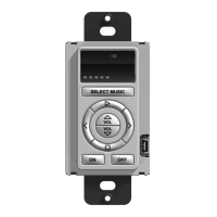
Water Resistant In-Wall Keypad
WK2 Glass Keypad
Assembly
Holes (4) used for
alternate mounting
methods (Use #4
athead screws)
WK2 Glass Keypad Assembly - Front View
 Loading...