7
FIGURE 8
FIGURE 7A
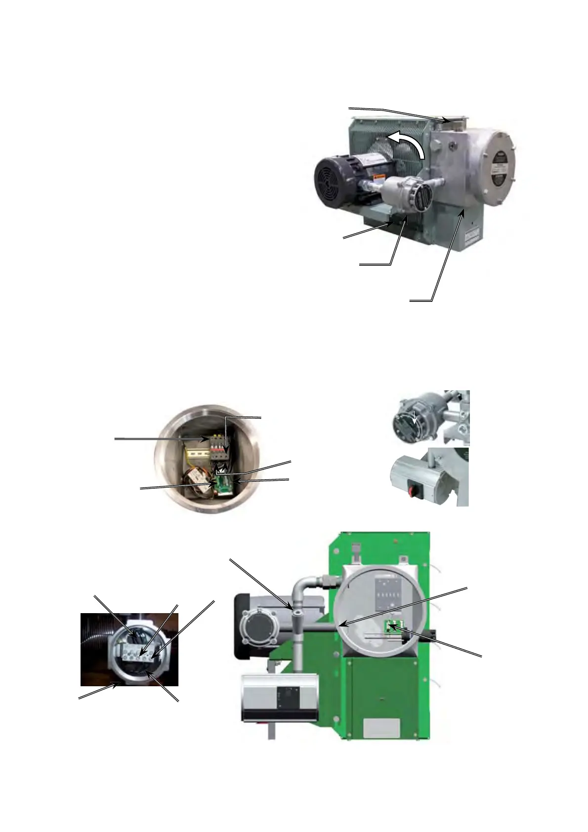
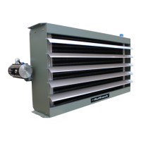
FIGURE 6
Optional factory
installed built-in
room thermostat.
Optional factory
installed built-in
disconnect.
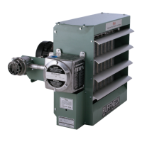
3. Heater may be supplied with a factory installed built-in integral
disconnect. (See Figure 7B)
Field Wiring for Integral Disconnect:
a. Power Supply conductors and Ground conductor pass through
M32 opening of Disconnect Enclosure (see Figure 7B). Supply
conductors to be wired to Disconnect Switch inside. Ground
conductor to be wired to Ground Lug fastened to inside of
Disconnect Enclosure.
b. If applicable, Remote Room Thermostat conductors pass
through 3/4"NPT opening (see Figure 7B) and are to be wired to
printed circuit board terminals marked “T’STAT”.
c. To reduce risk of ignition of hazardous atmospheres, conduit
runs must have a sealing fitting connected within 18 inches (457
mm).
Factory installed conduits require no further sealing. Integral
Disconnect is sealed at factory.
4. The internal grounding terminal in the control enclosure (or in the
integral disconnect enclosure when this option is provided) shall
be used as the equipment grounding means. An external bonding
terminal is provided for a supplementary bonding connection where
local authorities permit or require such a connection.
FIGURE 7B
Optional Built-in Disconnect
& Field Wiring
FINAL INSPECTION
1. Before application of electrical power:
a. Check that all connections are secured and comply with the
applicable wiring diagram (see Figure 9) and code requirements,
b. Confirm that the power supply is compatible with the data plate
rating of the heater,
c. Remove any foreign objects from the heater,
d. Install all covers and verify that all enclosures are well secured, and
e. Ensure that the fan rotates freely. See Figure 6 for proper direction
of fan rotation.
Sealed at Factory
3/4" NPT
(Remote Room
Thermostat
if applicable)
Terminals marked
“T’STAT”
Switch load side
terminals, this
side for factory wiring
only.
M32
(Power Supply)
Connect Supply Conductors to
this side of Switch
For a 1-phase heater use these
Switch terminals
Air
intake
Fan
rotation
Rear View of Heater
M32 opening
for field wiring
Motor
junction box
Control enclosure
and cover
Do not install conduit below heater (see Figure 3).
Air exits through
louvers.
Connect supply conductors
to this side of contactor.
For a 1-phase heater, use
these contactor terminals
Contactor load
side terminals,
this side for
factory wiring
only.
Active and spare
fuses (see parts list)
Printed circuit board’s
terminal block
Control Enclosure & Field Wiring