EasyManua.ls Logo

Rugby LR-26B - User Manual

Default Icon
19 pages
Print Icon
To Next Page IconTo Next Page
Loading...
03 5804
LR-26B, LR-27B, LR-28A, or LR-623
INSTALLATION AND
OWNER'S MANUAL
To Be Filled In By Installer
Hoist Installed:
Hoist Serial #:
Pump Installation & Operation Manual #:
In-Service Date:
Dealer:
Address:
Dealer Phone#:
Use this manual ONLY if installing or operating an LR-26B, LR-27B, LR-28A, or LR-623 hoist. If
installing or operating a model SF-26B, SF-28A, or SF-623 Sub-frame hoist, refer to manual #03
6077. This manual should be kept in truck glove compartment for reference when needed.
Features LR-26B(03 1440),LR-27B(03 1484),LR-28A(03 1439),LR-623(03 2040)
First Edition: August 1, 1996
Latest Edition: 7 (October 31, 2001)
INDUSTRIAL PARK
515 1ST STREET NORTH EAST
RUGBY, ND 58368
Question and Answer IconNeed help?

Do you have a question about the Rugby LR-26B and is the answer not in the manual?

Overview

This document serves as the Installation and Owner's Manual for Rugby Manufacturing Co. hoists, specifically models LR-26B, LR-27B, LR-28A, and LR-623. It provides comprehensive instructions and warnings for the proper installation, operation, and maintenance of these hoists, which are designed for use without a sub-frame. For sub-frame hoist models (SF-26B, SF-28A, SF-623), a separate manual (Part #03 6077) should be consulted.

Function Description:

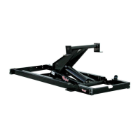
The LR-series hoists are designed to facilitate the dumping of material from truck bodies. They operate by lifting the truck body to a specified dump angle, allowing gravity to unload the contents. The manual details the installation of the hoist frame, rear hinge, and lifting shaft assemblies, which are critical components for the hoist's mechanical operation. The hydraulic system, while essential for the hoist's function, is covered in separate manuals depending on its type (drive shaft driven, direct mount, electric double acting, or electric single acting). The manual emphasizes the importance of compatible hydraulic components for safe and effective operation.

Important Technical Specifications:

  • Hoist Models Covered: LR-26B, LR-27B, LR-28A, LR-623.
  • Manual Stock Number: 03 5804.
  • First Edition: August 1, 1996.
  • Latest Edition: 7 (October 31, 2001).
  • Hoist Features (Part Numbers):
    • LR-26B: 03 1440
    • LR-27B: 03 1484
    • LR-28A: 03 1439
    • LR-623: 03 2040
  • Rear Hinge Dimensions: 38 1/16" wide, centered side to side in the truck chassis frame rail notch.
  • Longsill Spacing: Hinge assembly designed for 34" truck longsill spacing.
  • Hoist Mounting Height:
    • LR-26B & LR-27B: At least 7 1/4" clearance above truck frame.
    • LR-28A: 8 1/4" clearance above truck frame.
    • LR-623: 8" clearance above truck frame.
  • Clearance between Truck Cab and Body: At least 2" required.
  • Hydraulic Parameters (General Guide):
    • LR-27B:
      • Maximum Hydraulic Flow Rate: 12 GPM
      • Maximum Pressure for Raising: 2350 PSI
      • Maximum Pressure for Lowering: 750 PSI
    • LR-26B, LR-28A, LR-623:
      • Maximum Hydraulic Flow Rate: 9 GPM
      • Maximum Pressure for Raising: 3200 PSI
      • Maximum Pressure for Lowering: 1000 PSI
  • Cylinder Specifications:
    • LR-26B & LR-27B: 6" dia. piston; 20" stroke.
    • LR-28A: 6" dia. piston; 28" stroke.
    • LR-623: 6" dia. piston; 23" stroke.
  • Recommended Long Beams:
    • LR-26B & LR-27B: 6" long beams.
    • LR-28A & LR-623: 7" long beams.
  • Cab Axle (CA) Range:
    • LR-26B & LR-27B: 102" to 120" CA.
    • LR-28A: 114" to 138" CA.
    • LR-623: 10' to 18' box (CA not explicitly stated but implied by box length).
  • Box Length Range:
    • LR-26B & LR-27B: 13' to 16' box.
    • LR-28A: 16' to 18' box.
    • LR-623: 10' to 18' box.
  • Dump Angle Range: 40° to 50° for all models.
  • Mounting Configurations: Standard and Reverse Mounting, with corresponding "M" dimensions (distance between rear hinge center and saddle center) provided for various dump angles.
  • Parts List (Common Components):
    • Cotter Pin (5/16" x 3 1/2")
    • Lock Washer (1/2")
    • Hex Locknut (5/8")
    • Hex Nut (1/2")
    • Set Screw (3/8")
    • Hex Cap Screw (5/8 x 4 Gr. 8 PLTD or 5/8 x 4 1/2 Gr. 8 PLTD for LR-28A)
    • Hex Cap Screw (1/2 x 1 1/2 Gr. 5 PLTD)
    • Grease Fitting (1/4" Thread Forming)
    • Mounting Angle
    • Lifting Shaft Assembly
    • Lock Collar
    • Cylinder Pinning Shaft
    • Frame Assembly
    • Cylinders (specific to model, e.g., 6" x 20" for LR-26B/27B, 6" x 28" for LR-28A, 6" x 23" for LR-623)

Usage Features:

  • Installation Process:
    1. Mark rear hinge location (approx. 32" behind center of rear axle on single axle trucks).
    2. Cut notches in truck chassis frame rails.
    3. Weld rear hinge angle into notches.
    4. Slide lock collars and lifting shafts into hoist lifting tube.
    5. Position hoist on truck frame, ensuring centering and squaring.
    6. Place mounting angles under saddle and secure to truck frame with bolts.
    7. Weld mounting angles to hoist saddle brackets.
    8. Position and secure liner (sleeper) to truck frame to achieve required hoist clearance.
    9. Position body with long beams onto truck frame, ensuring cab clearance.
    10. Attach rear hinge brackets to long beams by welding.
    11. Weld lifting shaft assemblies to body long beams, then secure lock collars.
    12. Remove temporary 1/2" X 1 1/2" hex cap screw from saddle tube and plug the hole to enable the "anti-kick up device."
    13. Install body prop(s) as per separate manual (Part #03 6034).
  • Mounting Configurations: The manual provides tables for both "Reverse Mounting" and "Standard Mounting," detailing the "M" dimension (distance between rear hinge center and saddle center) for various dump angles (40°, 45°, 50°).
  • Hoist Movement Considerations: During the initial degrees of the dump cycle, the lower link moves forward in standard mounting and rearward in reverse mounting. The manual warns to keep these areas clear to prevent damage.
  • Adjustability: Hoist saddle brackets can be rotated to sit flat on the truck frame by loosening a 1/2" x 1 1/2" hex cap screw (which is later removed). Moving the hoist along the truck frame affects performance: forward movement reduces dump angle and increases capacity, while rearward movement increases dump angle and decreases capacity.
  • Safety Warnings:
    • Welding/Cutting/Grinding: Always take steps to prevent fuel ignition.
    • Exhaust Heat: Install hydraulic components away from exhaust heat to prevent failure and fire.
    • Working Under Raised Body: NEVER position yourself or others under a "loaded" body. ALWAYS use body prop(s) on an "unloaded" body.
    • Faulty Equipment: Repair faulty equipment before use; consult manufacturer if needed.
    • Overloading: NEVER exceed Gross Vehicle Weight (GVW) or Gross Axle Weight (GAW) ratings.
    • Incorrect Installation/Operation: Can cause damage, injury, or death. ALWAYS follow manufacturer's instructions.
    • "Anti-Kick Up Device": Failure to remove the temporary screw from the saddle tube will prevent this device from functioning, potentially causing damage.

Maintenance Features:

  • Lubrication:
    • Install and grease 10 grease fittings in the hoist frame.
    • Install and grease 2 grease fittings in the truck rear hinge.
    • All grease fittings should be greased periodically, or at least every time the truck is greased.
  • Hydraulic Oil:
    • Check oil level in the pump reservoir every time the truck engine oil is changed.
    • REMEMBER TO KEEP THE OIL CLEAN.
    • An annual oil change is recommended to prevent contaminants from damaging the pump and hoist cylinder.

Rugby LR-26B Specifications

General IconGeneral
BrandRugby
ModelLR-26B
CategoryAutomobile Accessories
LanguageEnglish

Related product manuals